

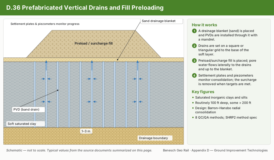
Prefabricated Vertical Drains (PVDs), also known as wick drains, are band-shaped products consisting of a geotextile filter jacket surrounding a plastic drainage core. Installed on a grid through soft, compressible foundation soils, they shorten the length of the drainage path so that pore water can escape radially to the drain rather than only migrating vertically — cutting the time needed to reach a target degree of consolidation from years to months. PVDs are almost always paired with fill preloading: temporary surcharge fill placed on top of (or in place of) the final embankment section to increase the driving stress and speed up settlement before the permanent pavement or structure is built. The technology provides no structural reinforcement of its own; site stability during filling still depends on the soft soil's shear strength keeping pace with the rising fill load.
The summaries below are organized by source document, all part of FHWA/SHRP2's “R02: Geotechnical Solutions for Soil Improvement, Rapid Embankment Construction, and Stabilization of Pavement Working Platform” reference series, the same series behind the other technique pages in this library. They're a starting point for understanding the technology and its design logic — not a substitute for a project-specific geotechnical design or a licensed engineer's review.
At a glance
- Basic function: band-shaped drains shorten the drainage path in soft, saturated foundation soils, accelerating consolidation settlement and shear-strength gain under a temporary surcharge or preload
- Geologic applicability: saturated, low-strength, inorganic clays and silts; routinely installed to 100 feet, with some projects exceeding 200 feet
- Design basis: genuine FHWA-preferred design procedure — the One Dimensional Model, based on Terzaghi-Barron/Barron-Hansbo consolidation theory (Elias et al. 2006; Rixner et al. 1986)
- QC/QA basis: genuine FHWA-preferred guidance (Rixner et al. 1986); 8 individual QC/QA methods are summarized, ranging from simple settlement plates and surveying to piezometers, inclinometers, and field vane shear testing on more sensitive or higher-risk sites
- Specifications: a single, comprehensive SHRP2-developed Standard Method Approach Specification template on file — no side-by-side comparison of competing specifications is needed
- Cost data: genuine cost-range table, historical bid data from five state DOTs, and a conceptual cost-estimating spreadsheet link — one of the more complete cost treatments in this library
- Alternate technologies: deep foundation elements, sand drains, vacuum preloading, stone columns, deep dynamic compaction, grouting, deep soil mixing, excavation and replacement, and lightweight fill
- Example application: Airport Runway and Taxiway Extension, Moline, IL (full case history on file)
Supplementary Graphics
GHRM · Section 17.16.36 · 3 graphics
▼
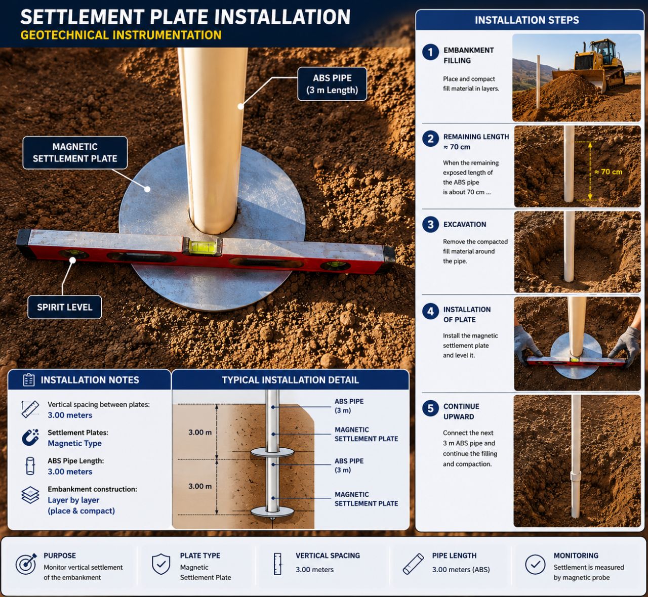
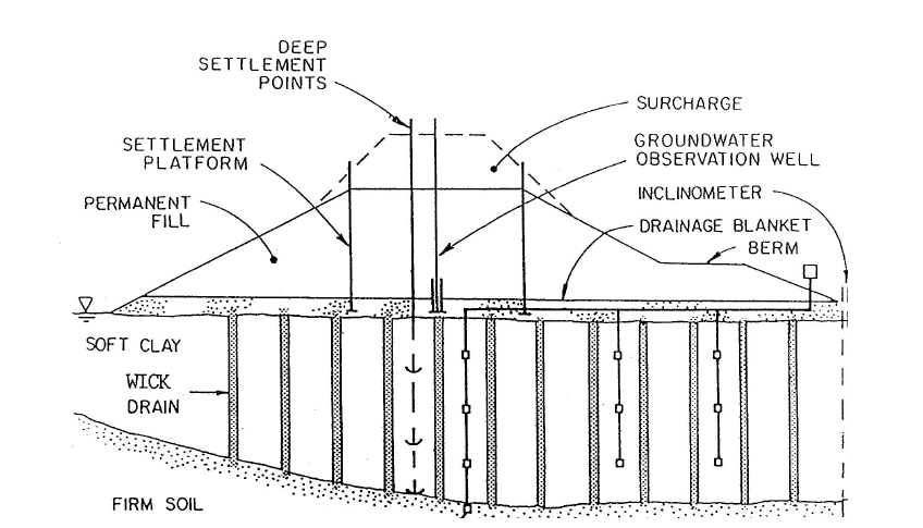
Supplementary graphics for GHRM Section 17.16.36 (Ground Improvement Technologies). The schematic summarizes how the technique works using the typical values documented on this page; the reference infographics are from the Named Graphics library. Click any graphic to enlarge.
Prefabricated Vertical Drains and Fill Preloading — Technology Fact Sheet
GeoTechTools.org · November 2012
▼
Basic function: Prefabricated Vertical Drains (PVDs), a.k.a. wick drains, are used to accelerate the settlement and shear strength gain of saturated, soft foundation soils by reducing the drainage path length. Fill preloading consists of placing temporary fill on top of the embankment to speed settlement in the foundation soils.
| Advantages | Potential disadvantages |
|---|---|
| Decreased construction time | Stiff soil layers increase installation difficulty leading to increased cost |
| Low cost | Limited headroom can be a limitation |
| No spoil | Settlements observed in field generally do not match oedometer tests |
| High production rate | |
| Durable | |
| Simple QC/QA procedures |
Geologic Applicability
Saturated low strength, inorganic clays and silts. PVDs are routinely installed to depths of 100 feet (30.5 meters), and have been installed to more than 200 feet (61 meters) on some projects.
General Description
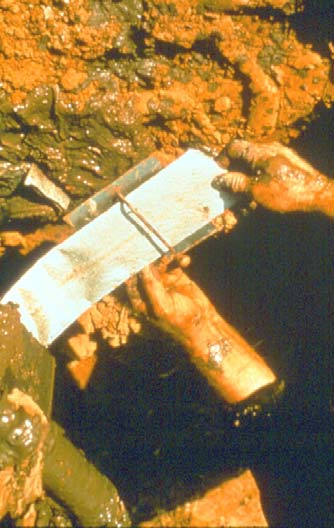
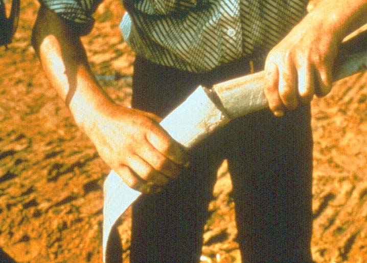
PVDs are band shaped (rectangular cross-section) products consisting of a geotextile filter material surrounding a plastic core.
Construction Methods
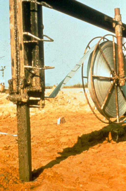
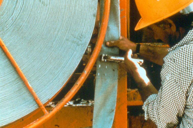
Installation of PVDs requires site preparation, construction of a drainage blanket and/or a working mat, and installation of the drains. Site preparation includes removal of vegetation and surface debris, and obstacles that would impede installation of the PVDs. It may be necessary to construct a working mat to support construction traffic and installation rig loads, which can later serve as the drainage blanket. There are many different ways of installing PVDs, but most methods employ a steel covering mandrel that protects the PVD material as it is installed. All methods employ some form of anchoring system to hold the drain in place while the mandrel is withdrawn following insertion to the desired depth. The mandrel is penetrated into the compressible soils using either static or vibratory force.
Additional Information
Design considerations include drain spacing, flow resistance and installation disturbance. Quality control tests usually relate to the material properties of the drain and the measurement of settlement and pore pressures during consolidation. Factors which affect the unit cost of installing PVDs include: the type, strength and depth of the soil, the specifications and requirements, the size of the project, material cost, and labor cost. The installed costs of PVDs are in the range of $2.50 to $3.25 per meter. Mobilization costs will typically range from $8,000 to $10,000 plus the cost of instrumentation and installation of a drainage blanket.
SHRP2 Applications
Embankment and roadway construction over unstable soils; roadway and embankment widening.
Example Successful Applications
Airport Runway and Taxiway Extension, Moline, IL.
Complementary Technologies
PVDs with a preload are typically not used in conjunction with other technologies.
Alternate Technologies
Deep foundation elements, sand drains, vacuum preloading, stone columns, deep dynamic compaction, grouting, deep soil mixing, excavation and replacement, and lightweight fill.
Key references for this fact sheet: Elias et al. (2006); Massarsch and Fellenius (2005); Rixner et al. (1986). (See the Bibliography note below regarding Massarsch and Fellenius 2005.)
Prefabricated Vertical Drains and Fill Preloading — Design Guidance
FHWA-preferred procedure: the One Dimensional Model (Terzaghi-Barron/Barron-Hansbo theory)
▼
The FHWA has design documents covering the preferred design procedure for this technology: Prefabricated Vertical Drains (Rixner et al. 1986, FHWA-RD-86-168) and Ground Improvement Methods, Volume 1 (Elias et al. 2006, FHWA NHI-06-019).
Table 1 — Typical Design Inputs & Outputs▼
| Category | Typical inputs / outputs |
|---|---|
| Performance criteria/indicators | Settlement rate; settlement magnitude; undrained shear strength |
| Subsurface conditions | Soil stratigraphy; size of area to be improved; groundwater table elevation; initial total/excess pore pressure with depth; vertical, horizontal, and smear zone permeability; void ratio; initial unit weight; moisture content; organic content; compression and secondary compression indices; coefficient of vertical and horizontal consolidation; compressibility; preconsolidation pressure; at-rest horizontal earth pressure coefficient; Atterberg indices; SPT N-count; CPT values; undrained shear strength; Young's modulus; Poisson's ratio |
| Loading conditions | Traffic load; embankment pressure; structure loads; earthquake acceleration and duration |
| Material characteristics | PVD permittivity; PVD tensile strength/durability; discharge capacity; well resistance/discharge factor; disturbance factor; preload material |
| Construction techniques | Drainage blanket material; PVD installation; preload staging |
| Geometry | Spacing; PVD length; PVD thickness and width; well diameter; equivalent well diameter; smear zone diameter; spacing influence factor; fill preload height; drainage blanket height; amount of primary consolidation; amount of secondary compression |
One Dimensional Model. Current FHWA reference(s): Elias et al. (2006); Rixner et al. (1986). Supporting reference(s): Arulrajah et al. (2004); Bergado and Patawaran (2000); Chu et al. (2002a); Chu et al. (2004); Hansbo (1979); Hansbo (1986); Hansbo (2004); Holtz et al. (1991); Indraratna et al. (2007); Lin et al. (2006); Wang and Jiao (2004); Welsh (1987).
The use of PVDs with a preload is an economical and beneficial solution when the time to reach desired consolidation without vertical drains is too great. The goal of PVD design is to reduce the length of the drainage path in order to accelerate consolidation. Design parameters include the selection of the drain type, drain spacing, drain length, and the amount of preload needed to achieve a specified consolidation within an allotted time. The design method begins with traditional settlement analyses without PVDs to determine the total magnitude and time rate of settlement under final project loads; the use of PVDs is then considered to reduce the time to reach the final settlement through reduction in the length of the drainage path. The conventional method follows the Terzaghi-Barron theory developed for sand drains in soft soils, wherein radial drainage and one-dimensional consolidation are assumed.
PVD spacing can be determined using the Barron-Hansbo relationship that relates the time to achieve a desired average degree of consolidation to drain diameter, drain spacing, and coefficient of consolidation:
The term Fs is a function of ds, the radius of the smear zone, and accounts for soil disturbance in highly plastic and sensitive soils, where it is usually given the value of 2. If the value of ch has been accurately determined or is given a highly conservative value, Fs can be ignored. Because of advances in PVD design, the well resistance (Fr) can usually be considered insignificant and can be ignored. Chu et al. (2004) provides guidance for when Fr and Fs should be considered in the design calculations. Methods to assess ch include lab tests as detailed in Table 6 of Rixner et al. (1986); relationships between the coefficient of consolidation in the vertical direction (cv), the liquid limit, and ch are given in Elias et al. (2006).
With the Barron-Hansbo equation, the soil properties (ch), time (t), and design requirements (Ūh) are held constant while the drain spacing factor (F(n)) is varied. It is assumed that F(n) = ln(n) − 0.75, where n is the spacing influence factor — the ratio of the equivalent well diameter (de) to the well diameter (dw). The equivalent well diameter is 1.05 times the spacing between each drain for an equilateral triangular spacing and 1.13 times the spacing between drains for a square spacing pattern. The well diameter is the equivalent circular drain size for a PVD and is typically approximated as:
The spacing influence factor (n) has a significant effect on the consolidation rate and should be carefully considered during design. The radius of the smear zone, ds, is difficult to quantify, as it is affected by the shape and size of the mandrel, the type of soil, and the sensitivity of the soil. Chu et al. (2004) present multiple theories to approximate ds, ranging from ds=2dw to 5–8 times dw. Lin et al. (2006) suggest approximating ds as twice the diameter of the mandrel, and propose an equivalent horizontal permeability of surrounding soils (ke) that incorporates the radius of the mandrel, ds, de, and the horizontal and smear zone permeability (kh and ks). Wang and Jiao (2004) present an equation for an equivalent horizontal permeability as a function of radial distance, based on the assumption that soil permeability changes continuously (more representative of actual conditions), typically breaking the permeability into two zones (smear zone and undisturbed). Once consolidation is underway, the Asaoka method can be used to give updated values of ch based on settlements as they occur, using Figure 8 in Elias et al. (2006).
Increasing the surcharge loading or decreasing the PVD spacing will increase the rate of consolidation. If spacing is kept constant but the surcharge is increased, the time period needed to attain the desired settlement will decrease; however, decreasing PVD spacing is not always a viable method for increasing the rate of consolidation. Arulrajah and Bo (2008) demonstrate through back-analysis that the value of ch decreases for smaller PVD spacing — spacing drains too closely can be counterproductive, as close spacing increases the ratio of the smear zone to the undisturbed zone, which can decrease the rate of pore water pressure dissipation. If the time available for preloading needs to be shortened, increasing the surcharge is recommended instead.
The PVDs do not provide any reinforcement and serve only to increase the rate of consolidation. Stability failures along the perimeter of the preloaded area must be prevented throughout the filling and consolidation process, which requires that the shear strength of the underlying soft soil be adequate to support the overlying fill slopes. On many projects this is only possible either by controlling the rate of filling so soft-soil strength gain from consolidation can keep up with the rising demand for shear strength as fill height rises, or by construction of stability berms around the fill. Continuous monitoring of the actual rates of pore pressure dissipation and settlement is essential; monitoring techniques include measuring the displacement ratio and reading inclinometers (see the QC/QA Procedures section).
A concern during design is that if the engineer does not account for stress-dependent variations in compressibility and permeability, performance predictions are unlikely to coincide with field drainage processes. Since compressibility and permeability vary in the same direction, the ratio k/mv (and the coefficient of vertical consolidation, cv) may remain reasonably constant; more common sources of discrepancy between predictions and actual field performance are non-linearity in stress-strain behavior, large strains, and secondary compression, along with uncertainty in approximating soil parameters rather than oversimplifications in the theory itself.
Prefabricated Vertical Drains and Fill Preloading — QC/QA Procedures
FHWA-preferred guidance (Rixner et al. 1986); 8 individual QC/QA methods are summarized
▼
The FHWA's Prefabricated Vertical Drains document (Rixner et al. 1986), pages 68–71, addresses construction monitoring and is considered the best available QC/QA guidance for PVD and fill preloading in support of the SHRP2 objectives. Quality Control (QC) refers to procedures, measurements, and observations used by the contractor to monitor and control construction quality; Quality Assurance (QA) refers to measurements and observations by the owner or the owner's engineer to provide assurance that the facility has been constructed in accordance with the plans and specifications.
| Category | Items |
|---|---|
| Existing QC — Material related | Consolidation test results; shear strength test results; PVD material testing |
| Existing QC — Process control | Piezometer readings; surface settlement readings; installation records; construction and PVD observations |
| Existing QA — Material related | Consolidation test results; shear strength test results |
| Existing QA — Process control | Construction and PVD observations; installation records; piezometer readings; surface settlement measurements |
| Performance criteria — Material parameters | Final, in-situ degree of consolidation; in-situ shear strength |
| Performance criteria — System behavior | Embankment settlement; excess pore pressure |
| Emerging QC/QA — Material related | |
| Emerging QC/QA — Process control | Automated surveying and pore pressure readings |
A typical comprehensive QC/QA program for PVD and fill preloading projects varies based on size, complexity, and application of the improved site. Simpler projects not involving stability concerns or strict time constraints only require settlement monitoring and materials and construction inspection; more sensitive projects will utilize additional testing such as inclinometers, piezometers, determination of the Displacement Ratio, and/or surveying. An advanced program for large and high-risk projects should include materials testing, field vane shear tests or other soil-strength methods, piezometers, inclinometers, and, in some cases, field test sections. End result specifications are not usually used for PVD and preload projects, as they would require an extensive soil exploration (Elias et al. 2006).
Settlement magnitudes can be determined using surveying, settlement plates, and piezometers; data from these measurements verifies design settlement predictions and monitors project progress. A large number of case histories have shown a significant discrepancy between the rate of settlement and the rate of pore pressure dissipation — when this occurs, settlement data is typically given precedence. Piezometer readings can be influenced by pore gas, poor readings, collapse of soil structure, secondary compression, and structural viscosity. Settlement and pore water pressure readings should be taken for a period of time after the fill preload has been removed to monitor rebound.
For projects where stability is a concern, inclinometers and piezometers can be installed and measured; Elias et al. (2006) recommends installing inclinometers at the toe of the embankment or in front of retaining walls, with settlement plates and piezometers beyond the crest of the embankment and/or near the centerline. For sites where stability is especially a concern, Elias et al. (2006) provide a method to determine the Displacement Ratio — based on case history experience, a Displacement Ratio of 0.2 generally corresponds to a site factor of safety of 1.3, while higher ratios may indicate an unstable site.
Prior to installation, the quality of the PVD material and conformance to design specifications should be verified, and trial sections should be used to generate the best QC and installation standards. Field vane shear tests work well in assessing shear strength changes in the soil (time-dependent, increasing with time of consolidation); ASTM D2573 can be referred to for guidance.
Piezometer▼
Reference(s): Elias et al. (2006); Hansbo (2004); Holtz (1987); SHRP2 Phase I Technology Assessment (2008); Welsh (1987). Method summary: piezometers are used to measure and monitor pore water pressures before, during, and after preloading; once installed, they should be read on a regular schedule. By assessing excess pore water pressures before, during, and after preloading, the degree of consolidation can be determined. Interpretation requires knowledge of the site's loading history and pre-preloading pore water pressures.
Accuracy and precision: piezometers provide a good assessment of pore water pressure; readings can be influenced by the location of the water pressure transducer, but are not greatly influenced by the operator. Adequacy of coverage: limited — multiple piezometers are required laterally and at varying depths to provide a site profile. Implementation requirements: installation requires a drill rig and the necessary materials; once installed, the process to read piezometers is simple. General comments: Elias et al. (2006) note piezometers are used for both calculating achieved consolidation rate and detecting the excessive build-up of pore pressure that indicates potential failure.
Settlement Plates▼
Reference(s): Elias et al. (2006); Hansbo (2004); Holtz (1987); SHRP2 Phase I Technology Assessment (2008); Welsh (1987). Method summary: settlement plates should be placed at the bottom of the drainage blanket, the bottom of the compressible layer, and intermediate depths prior to PVD installation and preload, then read at established time intervals to monitor settlement progression.
Accuracy and precision: a reliable measurement of the total amount of settlement. Adequacy of coverage: depends on the number of plates used relative to the site's size. Implementation requirements: once installed, readings are easy to take. General comments: a good indicator of preloading progress and final results; reliability is highly contingent on the accuracy of the predicted design settlement. Elias et al. (2006) state that settlement measuring devices — platforms, deep settlement points, or horizontal deflection devices — are used to measure only the rate and total amount of consolidation.
Displacement Ratio▼
Reference(s): Elias et al. (2006). Method summary: calculating the Displacement Ratio (DR) is a method of evaluating the stability of sites where a fill preload is utilized, measured along and transverse to the perimeter of the fill. DR is defined as the maximum cumulative horizontal displacement of the inclinometer divided by the cumulative settlement determined from an adjacent settlement plate, measured during and after fill placement to monitor lateral movement. A significant increase in DR indicates site stability concerns; a DR of 0.2 or less generally indicates a stable site.
Accuracy and precision: as reliable as the underlying settlement plate and inclinometer readings. Adequacy of coverage: depends on the number of settlement plates used. Implementation requirements: the calculation itself is straightforward and simple. General comments: for sites where stability is a concern, the rate of load increase must be carefully monitored; according to Elias et al. (2006), a DR approaching 0.4 might be measured if fill is placed quickly.
Inclinometer▼
Reference(s): Elias et al. (2006); Holtz (1987). Method summary: inclinometers are installed in the soil and read at established time intervals to record lateral movements with depth.
Accuracy and precision: a reliable depiction of lateral movement with depth. Adequacy of coverage: limited — more inclinometers provide more information about lateral movement below the surface. Implementation requirements: obtaining and reducing data requires some experience. General comments: a good indicator of progress and final results for sites where slope stability is a concern; useful for identifying potential slope-stability problem areas where a surcharge load is used.
Material Testing▼
Reference(s): Chu and Choa (1995); Chu et al. (2004). Method summary: tests on PVDs obtain information on filter quality, discharge capacity, and tensile strength. For PVDs with an apparent opening size (AOS) greater than 40 µm, ASTM D4751 determines AOS; ASTM D4491 determines permeability; ASTM D4632 is often specified to measure tensile strength. Chu and Choa (1995) describe the buckled drain tester, which places the drain vertically in a clay-filled tester; as the surrounding clay consolidates the drain buckles, its discharge capacity is measured, and it is then excavated and inspected for damage.
Accuracy and precision: mixed — ASTM D4751 (AOS) is not always reproducible and receives a rating of L; ASTM D4491 (permeability) is reliable and accurate (rating H); ASTM D4632 (tensile strength) is a function of straining rate and moisture content (rating M); the buckled drain tester is reliable for short-term measurements but may not be feasible for predicting long-term discharge capacity. Adequacy of coverage: tests are conducted on PVDs intended to represent the batch to be installed in the field. Implementation requirements: specialized equipment and experience. General comments: the PVD is commonly delivered with manufacturer certificates; these testing methods are usually reserved for aggressive QC/QA programs and not performed on most projects. Discharge capacity should be tested at various pressures, since it can significantly decrease within as little as a month.
Material and Site Inspection▼
Reference(s): Elias et al. (2006); Holtz (1987). Method summary: records should be kept of equipment inspections, PVD material quality, PVD dimensions (width and thickness), mandrel dimensions and type, PVD installation depth, spacing, location, verticality of installed PVDs, drainage blanket material and placement conditions, and fill material and placement, in order to verify adherence to design. Any splicing of drains should be recorded.
Accuracy and precision: confirming material and construction quality is a straightforward and highly precise process, closely representing actual field conditions. Adequacy of coverage: records should be kept for every PVD installed and every preload lift placed; representative inspections are typical for materials arriving in bulk. Implementation requirements: keeping records is simple and necessary. General comments: once installed, PVDs are difficult to monitor, so inspecting materials before installation is a critical step; PVDs should have a continuous core and filter jacket and should not be used if damaged.
Surveying▼
Reference(s): Holtz (1987); SHRP2 Phase I Technology Assessment (2008). Method summary: plan and elevation surveys aid in controlling the rate of fill placement and preload removal, and can be used to detect settlement.
Accuracy and precision: highly accurate and precise. Adequacy of coverage: can cover a large area in a short amount of time. Implementation requirements: specialized equipment is necessary, but only minimal experience is required; surveying is a well-established and commonly used procedure. General comments: laser scanning is a more recent technology available to facilitate the surveying process.
Field Vane Shear Test▼
Reference(s): Yan and Chu (2003a, b). Method summary: field vane shear tests are performed in the field to determine the in-situ shear strength of the soil; specific guidelines can be found in ASTM D2573.
Accuracy and precision: dependent on the competence of the personnel and the quality of the equipment and facilities; values are time-dependent, with shear strength increasing with time of consolidation, which should be considered when analyzing results. Adequacy of coverage: assesses improvement only locally, so a testing program should include tests at a number of locations and depths across the site. Implementation requirements: a fairly simple concept, but requires specialized equipment and experience. General comments: works well for assessing shear strength changes in the soil; final shear strength values are a good indicator of the final results of a PVD and fill preloading project.
Prefabricated Vertical Drains and Fill Preloading — Specifications
Standard Method Approach Specification · V.2, August 5, 2011
▼
Review of existing specifications: most specifications reviewed were written by state DOTs, primarily based on the guide specification presented in FHWA's Ground Improvement Methods (Elias et al. 2006). Certain DOT specifications were particularly well written and included sections not present in the FHWA guide specification. Regardless of which PVD specification is used, it is recommended that the Bo et al. (2005), Holtz and Christopher (1987), Rixner et al. (1986), and Hansbo (1986) references be reviewed to ensure that all PVD material and installation requirements are included.
Preferred specification: the Standard Method Approach Specification for Prefabricated Vertical Drains and Fill Preloading is intended as a complete and fair specification, easily adaptable by the user for a specific project. It was generated by combining information from several recent DOT specifications and the Rixner et al. (1986) guideline specification, along with input from the SHRP2 R02 research team and advisory board. This is a fill-in-the-blank template (project-specific values such as durations, dimensions, and quantities are left for the user to specify); the summary below reproduces its organization and technical content rather than its blank fields.
Part 1 — General▼
Introduction & applicability: PVDs are band-shaped products consisting of a geotextile filter material surrounding a plastic core, installed to decrease the drainage path of the compressible soil layer and achieve a desired degree of consolidation (and corresponding shear-strength increase) within a specified time. Applicable soil types are cohesive soils of low strength and permeability. Applications include decreasing settlement time, decreasing the amount of surcharge or preload required to achieve a given settlement in a given time, decreasing secondary compression, and increasing the rate of strength gain from consolidation.
Standards and references: the specification allows for a project-specific selection of geotextile/geosynthetic test methods, including ASTM D3884 (abrasion resistance), D4632 (grab breaking load and elongation), D4533 (trapezoid tearing strength), D4833 (index puncture resistance), D3786 (Mullen burst), D4491 (water permeability/permittivity), D4751 (apparent opening size), D4595 (wide-width tensile properties), D4716 (in-plane flow rate/transmissivity), and D422 (particle-size analysis). Project drawings (foundation plans, earthwork and embankment plans, and other relevant drawings) and project geotechnical information are to be provided to the PVD contractor.
Definitions: Engineer — the Engineer of Record responsible for design of the highway embankments; Contractor — the company that installs the PVDs; QA Representative — the entity in charge of Quality Assurance, which in some cases may be the same as the Engineer.
Scope of work: the work consists of furnishing all necessary plant, labor, equipment, materials, incidentals, and transportation for PVD installation per the plans and specifications. Subsurface layers that limit penetration depth or transmit artesian water pressures to the surface may require special installation methods. The Contractor is responsible for determining and implementing the systems and criteria needed to meet specified methods and QC verifications, presenting any deviations in writing to the Engineer for review and approval.
Submittals: before the trial PVD installation, the Contractor submits full details of materials, equipment, sequence, and installation method, including rig size/type/weight/thrust, predrilling methods and equipment, mandrel dimensions, anchorage details, splicing methods, manufacturer literature on PVD properties, unspliced and spliced material samples, and qualifications of the Contractor and personnel.
Contractor requirements: for larger projects, the specification calls for a minimum number of years of documented PVD experience for the Contractor and superintendent, and evidence of prior PVD project experience, management/supervisory/key personnel experience, and installation to a comparable depth.
Measurement and payment: PVDs are measured by the linear foot, including the mandrel tip and PVD strip penetration below the approved top of the drainage blanket plus the specified cut-off length above it; predrilling is measured separately by the linear foot at locations actually predrilled. Payment is made at the contract unit price per linear foot for acceptable PVDs.
Part 2 — Equipment and Materials▼
Equipment: PVDs are installed using approved modern equipment causing minimum disturbance to the subsoil, maintaining the mandrel in a vertical position, using constant load or constant downward rate of advancement — vibrators, impact hammers, and jetting techniques are not permitted, since they may cause excessive disturbance and reduce horizontal hydraulic conductivity. A mandrel or sleeve protects the drain material from tears, cuts, and abrasion and retracts after each drain is installed; an anchor rod or similar arrangement at its bottom anchors the drain tip at the required depth during withdrawal. Predrilling or spudding through hard or dense materials may be required, but should not penetrate more than a specified distance into the underlying compressible soil. Trial PVDs are installed at each test location before production installation begins.
Materials — general: PVDs consist of newly manufactured materials: a continuous polyethylene or polypropylene plastic drainage core enclosed in or integrated with a non-woven geotextile jacket, with an aspect ratio (width divided by thickness) typically not exceeding 40–50. The jacket must allow free passage of pore water to the core without loss of soil material or piping, resist bending/punching/tensile forces, remain sufficiently rigid under lateral earth pressure while remaining flexible enough to bend smoothly during installation, and not crack, peel, or be susceptible to localized damage.
| Test item | Testing standard | Minimum average roll value |
|---|---|---|
| Minimum specific gravity | — | 0.95 |
| Minimum abrasion resistance | ASTM D3884 | 40 lbs. |
| Grab tensile strength | — | 120 lbs. |
| Elongation at break | ASTM D4632 | >50% |
| Minimum modulus | — | 600 lbs. at 10% elongation |
| Trapezoidal tear | ASTM D4533 | 50 lbs. |
| Puncture strength | ASTM D4833 | 38 lbs. |
| Mullen burst strength | ASTM D3786 | 130 psi. |
| Permittivity | ASTM D4491 | 0.45 sec-1 |
| AOS | ASTM D4751 | ≤ 100 sieve |
| Test item | Testing standard | Minimum average roll value |
|---|---|---|
| Core tensile strength | ASTM D4595 | 235 lbs. |
| Discharge capacity (at 50 psi) | ASTM D4716 | 1.5 gpm |
| Discharge capacity (at 25% compression) | ASTM D4716 | 1.5 gpm |
The mechanical properties of the assembled drain must equal those of the component jacket and core, and the assembled drain must resist wet rot, mildew, bacterial action, insects, salts, acids, alkalis, solvents, and other constituents in site groundwater. Only one type of assembled PVD is used per project. PVD rolls are labeled with lot/control number, roll number, date of manufacture, and product identification, and are wrapped and protected during shipping and storage; damaged material is rejected.
PVD drainage layer: a granular drainage layer is placed prior to PVD installation, meeting the following gradation (ASTM D422):
| Sieve | Percent passing |
|---|---|
| 2-inch | 100 |
| ½-inch | 65–100 |
| ¼-inch | 50–100 |
| No. 10 | 40–70 |
| No. 40 | 10–40 |
| No. 200 | 0–5 |
Part 3 — Execution▼
PVD installation process: planned PVD locations are staked and numbered; as-installed locations may not vary from plan locations by more than 6 inches, and drains exceeding that tolerance, or damaged or improperly installed drains, are rejected and abandoned in place, with replacements installed. PVDs are installed from the working surface to the plan depth (or as directed by the Engineer, who may vary depth, spacing, or drain count). The Engineer or QA Representative is provided a means of determining drain depth during installation, and receives a daily summary report of drain type, locations, installed lengths, any drains not reaching planned depth, and any locations where vibration/hammering/jetting was used. Equipment is plumbed before installing each drain (verticality tolerance of 5 inches in 10 feet). Only constant load or constant rate of advancement installation methods are used; vibration, hammering, or jetting are not permitted except in limited, approved circumstances. Drains are spliced by stapling to maintain structural and hydraulic continuity, with a maximum of one splice per drain, and are cut neatly at the working grade with a 4- to 8-inch protrusion above the drainage layer.
Pre-augering and obstructions: augering, spudding, or other approved methods loosen soil and clear obstructions, without penetrating more than two feet into the underlying compressible soil. When an obstruction is found, the Engineer is notified immediately, and the Contractor attempts to install an adjacent or offset drain (within two feet horizontally) before resorting to Engineer-directed obstruction-clearance procedures.
Artesian groundwater conditions: where PVDs would penetrate formations with hydrostatic head above ground surface, the design intent is to stop the PVDs above the artesian zone while maximizing penetration through the compressible layers; PVDs reaching artesian conditions are plugged, with drilling or grouting equipment on hand capable of sealing the PVD hole.
Field QA/QC: during installation trials, the Contractor demonstrates by proof testing with approved load cell equipment that its equipment can mobilize the minimum required net thrust; Engineer approval of equipment or sample materials does not relieve the Contractor of responsibility for correct installation. The PVD manufacturer must have produced a minimum quantity of PVD material (1,500,000 lineal feet in the template) used successfully within the past five years, and the Contractor must certify comparable installation experience and provide detailed project summaries for referenced projects. An experienced, full-time supervisor with comparable prior experience must be present at the work site at all times during installation, subject to the Engineer's approval.
This specification has been created as a basic template to aid state DOTs and other parties in creating complete, project-specific specifications; text in the source document marked as drafting guidance (and blank fields for project-specific values) has been summarized here in descriptive form rather than reproduced as fill-in-the-blank text.
Prefabricated Vertical Drains and Fill Preloading — Cost Information
GeoTechTools.org · November 2012 · cost ranges based on 2005–2010 data
▼
Commentary: the cost of PVDs on a highway project is typically captured in a contract bid item measured by the linear foot (LF), which usually includes incidental costs such as additional excavation and embankment to provide a level working surface or for temporary access routes, instrumentation for monitoring settlement, and augering through stiff upper soil layers (unless a separate pay item is used). Other costs that may be measured and paid for separately include mobilization, the drainage layer (granular material or horizontal strip drains), and surcharge embankment placement and removal.
Definitions: Preload — embankment material placed within the PVD installation area that is part of the final roadway cross-section. Surcharge — additional embankment placed above the design profile grade line, used to accelerate settlement and/or minimize secondary consolidation.
An average production rate for PVD installation ranges from 10,000 to 15,000 LF per day. Cost ranges below are based on data from 2005 through 2010; project-specific characteristics and constraints should be carefully examined, as they can significantly influence actual costs.
| Pay item | Quantity range | Unit | Low unit price | High unit price | Factors which may impact cost |
|---|---|---|---|---|---|
| Mobilization | 1 | Lump sum | $10,000 | $20,000 | Depths over 70 ft may require a crane instead of a modified hydraulic excavator; distances over 500 miles increase mobilization cost; phased projects may require multiple mobilizations; a crane may reduce production rate and raise unit cost |
| Prefabricated Vertical Drains | Greater than 10,000 | LF | $0.50 | $1.50 | A minimum of 10 ft overhead clearance beyond installation depth is required (less clearance multiplies cost); generally not feasible below 10,000 LF; quantities over 100,000 LF generally have lower unit costs; stiffer soils and obstructions reduce production rate and raise unit price |
| Granular Drainage Layer | 5,000 to 25,000 | Ton | $7.50 | $25.00 | Primarily sensitive to the cost of granular materials (including freight) |
| Horizontal Strip Drain | 5,000 to 25,000 | LF | $0.50 | $1.50 | Material type specified is the primary cost variable |
| Augered Holes | 1,000 to 10,000 | LF | $5.00 | $15.00 | Soil stiffness and obstructions may impact cost |
| Surcharge Embankment | 10,000 to 50,000 | CU YD | $3.00 | $10.00 | Haul distance and haul unit type for embankment are the primary cost variables |
| Surcharge Removal (waste) | 5,000 to 50,000 | CU YD | $3.00 | $10.00 | Haul distance/unit type to waste surcharge material; no additional project cost when surcharge can be reused within a project embankment, if sequencing allows |
| Pay item | Quantity | Unit | Low unit price | High unit price | Average unit price | No. of bids | Bid date | Source/agency |
|---|---|---|---|---|---|---|---|---|
| Special — Wick Drain | 31,600 | FT | $0.50 | n/a | n/a | 1 | 4/1/2010 | Ohio DOT |
| Special — Wick Drain | 83,100 | FT | $0.49 | $1.05 | $0.64 | 8 | 11/22/2006 | Ohio DOT |
| Special — Wick Drain | 452,735 | FT | $1.05 | $2.30 | $1.51 | 13 | 2/8/2006 | Ohio DOT |
| Misc. Wick Drain | 191,700 | LF | $0.42 | $1.25 | $0.56 | 3 | 2/5/2010 | Missouri DOT |
| Wick Drains | 145,000 | FOOT | $0.52 | $1.00 | $0.67 | 6 | 9/22/2005 | Oregon DOT |
| Surcharge Excavation | 5,000 | CUYD | $2.00 | $25.00 | $13.42 | 6 | 9/22/2005 | Oregon DOT |
| Wick Drains | 80,893 | FOOT | $0.62 | $0.93 | $0.70 | 8 | 3/24/2005 | Oregon DOT |
| Granular Drainage Blanket (Surcharge) | 7,042 | TON | $9.25 | $16.90 | $10.97 | 8 | 3/24/2005 | Oregon DOT |
| Vertical Drainage Wicks | 146,971 | LF | $0.50 | $0.80 | $0.66 | 5 | 6/28/2006 | Florida DOT |
| Embankment Surcharge | 8,471 | CY | $12.00 | $35.00 | $23.60 | 5 | 6/28/2006 | Florida DOT |
Conceptual Cost Estimating Tool: a cost-estimating spreadsheet is provided for producing a preliminary project scoping estimate: www.geotechtools.org/documents/pvdfp_costtool_r1.xlsx. The tool can be based on the typical construction cost item values in the Cost Information product above or on user-specified cost values when known; users should read and understand the Cost Information product before using the estimating tool.
Prefabricated Vertical Drains: Airport Runway and Taxiway Extension
Quad City Airport, Moline, IL · constructed 2006
▼
Location: the Quad City Airport, Moline, Illinois. Owner / Contractor / Engineer: not recorded in the source case history. Year constructed: 2006.
Project summary/scope: a 1,000-foot runway extension was constructed to increase capacity. With land-use constraints on one end of the runway, construction required up to 15 feet of fill placement over a bluff. With concerns of post-construction settlement under the added fill, Prefabricated Vertical Drains were selected to accelerate consolidation.
Subsurface conditions: alluvial soils consisting of silty clay overlying fine sand. The upper 3.3 to 6.6 feet of silty clay had N-values ranging from 5 to 10 blows per foot and moisture contents ranging from 22 to 30 percent; the lower portion of the silty clay had N-values ranging from 1 to 4 blows per foot and moisture content ranging from 30 to 45 percent.
A small surcharge of 5.2 feet, along with PVDs, was selected to accelerate consolidation. Horizontal strip drains were used instead of a drainage blanket due to the limited availability and high cost of clean sand. The 12 by 1 inch strip drains connected to four rows of PVDs spaced in a 5-foot triangular pattern. These design parameters were selected to achieve a maximum total settlement of 14 inches within 6 months. Since the taxiway was not as critical as the runway extension, the project was split into two phases. Approximately 252,600 linear feet of PVDs were installed to an average depth of 23 feet, with nearly 10,000 PVDs installed in three weeks.
Alternate technologies considered: construction without PVDs, or excavation and replacement combined with surcharging.
Performance monitoring: settlement plates were used to determine the time rate of consolidation. Actual settlements ranged from 4 to 16 inches in 3 to 4 months.
Cost information: the project was bid on a per-drain basis at $11.50 per drain. Mobilization costs were $10,000. Horizontal strip drains were installed at $1.50 per foot.
Summary source: Elias, V., Welsh, J., Warren, J., Lukas, R., Collin, J. G., and Berg, R. R. (2006). Ground Improvement Methods, Federal Highway Administration, NHI-06-019 Vol I and NHI-06-020 Vol II, Washington, D.C.
Date case history prepared: November 2012. Unlike most case histories in this library, the Owner, Contractor, and Engineer fields were all left blank in the source document; every other field — subsurface conditions, design parameters, quantities, monitoring results, and cost data — is populated, making this one of the more complete case histories on file despite that gap.
Prefabricated Vertical Drains and Fill Preloading — Photographs
▼
Prefabricated Vertical Drains and Fill Preloading — Bibliography
51 references on file; 21 cited by name in this page's own summaries are listed in full
▼
The references below were identified and used to complete the technology summaries, assessments, and website documents on file for this technique. A reference matrix follows the reference list in the source document, cross-referencing each reference against topics such as design procedure, construction methods, QA/QC, and case history — as with every other technique page in this library, that matrix extracts from the source PDF as visually mangled, unparseable table fragments and is skipped here. Of the 51 references on file, the 21 below are cited by name in this page's own Design Guidance, QC/QA, and Specifications summaries and are listed in full; the remaining references cover additional authors including Asaoka, Atkinson and Eldred, Bergado (with Anderson, Miura, and Balasubramaniam), Calabria, Cedergren, the Canadian Geotechnical Society, Chai (with Shen, Miura, and Bergado; and with Miura alone), Chen and Tan, Chu (2009 solo), Chu (with Varaksin, Klotz, and Menge), Goughnour, Hansbo (1981 solo; and with Jamiolkowski and Kok), Indraratna and Redana, Koerner, Ladd, Lin (with Masud, Karim, Sriwiroj, and Chantawong, 2000), Liu and Chu, McGown and Hughes, Mitchell (with Cooke and Schaeffer), Nogami and Li, Saye, Schaefer et al., Smith and Rollins, Stark et al., Terashi and Juran, USACE, Ye (with Xu and Gao), and Yildiz.
- Arulrajah, A., Nikraz, H., and M.W. Bo (2004). “Factors affecting field instrumentation assessment of marine clay treated with prefabricated vertical drains.” Geotextiles and Geomembranes, vol. 22, no. 5, pp. 415–437.
- Arulrajah, A, and Bo, M.W. (2008). “Factors Affecting Consolidation Related Prediction of Singapore Marine Clay by Observational Methods.” Geotechnical and Geological Engineering, vol. 26, no. 4, p. 417.
- Bergado, D.T., and Patawaran, M.A.B. (2000). “Recent developments of ground improvement with pvd on soft Bangkok clay.” Proc. Intl. Seminar on Geotechnics in Kochi 2000, Kochi, Japan, October, 2000.
- Bo, M.W., Chu, J. and Choa, V. (2005). “Use of prefabricated vertical drains for the improvement of ultra-soft soil.” Proc. 6th International Conference on Ground Improvement Techniques, July 18–19, Coimbra, Portugal.
- Chu, J., Yan, S.W., and Yang, H. (2002a). “Closure on discussion on ‘Soil improvement by vacuum preloading for and oil storage system’.” Geotechnique, Vol. 52, No. 2, p. 151.
- Chu, J., Bo, M.W., and Choa, V. (2004). “Practical considerations for using vertical drains in soil improvements projects.” Geotextiles and Geomembranes, Vol. 22, 101–117.
- Chu, J. and Choa, V. (1995). “Quality control tests of vertical drains for a land reclamation project.” Compression and Consolidation of Clayey Soils, Proc. of an Int. Symp., Hiroshima, Japan, May 10–12, H. Yoshikuni and O. Kusakabe (Eds), A.A. Balkema, 43–48.
- Elias, V., Welsh, J., Warren, J., Lukas, R., Collin, J. G., and Berg, R. R. (2006). Ground Improvement Methods, Federal Highway Administration, NHI-06-019 Vol I and NHI-06-020 Vol II, Washington, D.C., pp. 536 (Vol I) and 520 (Vol II).
- Hansbo, S. (1979). “Consolidation of Clay by Band-Shaped Prefabricated Drains.” Ground Engineering, 12(5), pp. 16–25.
- Hansbo, S. (1986). “Preconsolidation of Soft Compressible Subsoil by the use of Prefabricated Vertical Drains.” Annales des Travaux Publics de Belgique, Issue 6, p. 553.
- Hansbo, S. (2004). “Band drains.” Chapter 1 in Moseley, M.P. and Kirsch, K. (Editors), Ground Improvement, 2nd Edition, Spon Press, New York, pp. 4–56.
- Holtz, R.D. (1987). “Preloading with Prefabricated Vertical Strip Drains.” Geotextiles and Geomembranes, Vol. 6, Issue 1, p. 109.
- Holtz, R.D. and Christopher, B.R. (1987). “Characteristics of prefabricated drains for acceleration of consolidation.” Proceedings of the 9th European Conference on Soil Mechanics and Foundation Engineering, Vol. 2, Dublin, Ireland, pp. 903–916.
- Holtz, R.D., Jamiolkowski, M.B., Lancellotta, R., and Pedroni, R. (1991). “Prefabricated Vertical Drains: Design and Performance.” Construction Industry Research and Information Association.
- Indraratna, Sathananthan, Iyathurai, Buddhima, Rujikiatkamjorn, and Cholachat (2007). “Evaluation of Smear Zone Extent Surrounding Mandrel Driven Vertical Drains Using the Cavity Expansion Theory.” International Journal of Geomechanics, Vol. 8, Issue 6.
- Lin, D.G., Liu, W.T., and Lin, P. C. (2006). “Numerical Analyses of PVD Improved Ground at Reference Section of Second Bangkok International Airport.” Geotechnical Engineering, Vol. 37, No. 3, pp. 157–170.
- Rixner, J.J., Kraemer, S.R. and Smith, A.D. (1986). “Prefabricated Vertical Drains.” U.S. Department of Transportation, Federal Highway Administration, Research, Development and Technology, Vol. I: Engineering Guidelines, Report No. FHWA/RD-86/168.
- Wang, X-S. and Jiao, J.J. (2004). “Analysis of soil consolidation by vertical drains with double porosity model.” International Journal for Numerical and Analytical Methods in Geomechanics, 28, 1385–1400.
- Welsh, J.P. (1987). “Soil improvement – A Ten Year Update.” Geotechnical Special Publication No. 12, ASCE, New York.
- Yan, S. and Chu, J. (2003a). “Experience gained from two vacuum preloading projects.” Proceedings 12th Asian Regional Conf. on Soil Mechanics and Geotechnical Engineering, August 4–8, Singapore, 195–198.
- Yan, S. and Chu, J. (2003b). “Soil improvement for a road using the vacuum preloading method.” Ground Improvement, UK, Vol. 7, No. 4, 165–172.
Two references are cited by name elsewhere on this page but do not appear in this technique's own Bibliography document on file. Massarsch, K.R. and Fellenius, B.H. (2005), “Deep vibratory compaction of granular soils,” Chapter 19 in Ground Improvement – Case Histories, Elsevier, is listed as a Key Reference in the Technology Fact Sheet. The “SHRP2 Phase I Technology Assessment (2008)” is cited as a reference for the Piezometer, Settlement Plates, and Surveying QC/QA methods. Both are reproduced here as they appear in their respective source documents, which are likely drawing on foundational or shared references not separately tracked in this particular technique's bibliography.