
Geotechnical engineering libraryContact
 benesch
Appendix A is a borehole log template, Appendix B a laboratory test results table template, and Appendix C boilerplate Geotechnical Special Provisions (GSP) text.
The ground improvement technology sheets formerly listed here as Appendix D are now part of Chapter 17 — Ground Improvement Methods, Section 17.16.
Apps on dirtbert.com that support this chapter. Each one runs in a web browser on a desktop or a phone, with nothing to install. How to use the apps (I.3). Tools marked TOOLS open in the Geotechnical Analysis Suite (Benesch sign-in); the orange card below lists each one by section.
NANCY pages ask you to accept the Use and Disclaimers once in each browser.
Calculators and workbook tools from the Benesch Geotechnical Analysis Suite that support this chapter: 0 interactive calculators and 4 workbook guides. Each one is also placed inside the section it supports, in an orange tools strip.
| FF | Boring Data Summary SheetUsed in APPENDIX A — BOREHOLE LOG TEMPLATE | guide only | Guide |
| FF | RR Boring Info (blank)Used in APPENDIX A — BOREHOLE LOG TEMPLATE | guide only | Guide |
| DT | Data — Template (CSX)Used in APPENDIX B — LABORATORY TEST RESULTS TABLE TEMPLATE | guide only | Guide |
| PM | Calculation Sheet (blank)Used in APPENDIX C — GEOTECHNICAL SPECIAL PROVISIONS (GSP) TEMPLATE | guide only | Guide |
Tools open on dirtbert.com and need the Benesch sign-in. Drafts pending Benesch final review, not for use in design.
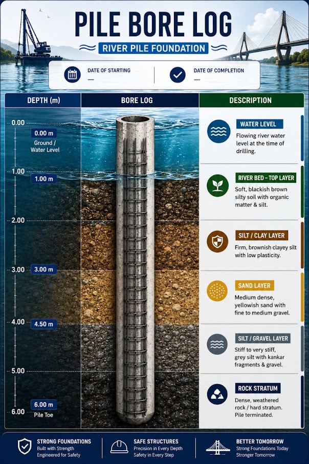
↗ Open printable boring log template (letter landscape)
 benesch
| ProjectExample Siding Extension — Embankment Widening | Benesch project no.000000.00 | Client railroad[Railroad] | Subdivision / MP[Sub.] MP 000.0 |
| Station / offsetSta. 00+00, 25 ft Lt. of CL main | Latitude / longitude00.00000° / −00.00000° | Ground surface elev. (ft)745.0 (NAVD 88) | Total depth (ft)25.0 |
| Drilling contractor[Contractor] | Rig / methodTrack-mounted rig / 3¼-in. HSA; NX core | HammerAutomatic, 140 lb, 30 in. drop | Energy ratio (ER)55% (calibrated) |
| Date started / completed__/__/____ / __/__/____ | Logged by[Name], [Title] | Checked by[Name], P.E. | Weather[Conditions] |
| Elev.ft | Depthft | Graphic log | Sample | SPT (ASTM D1586) | Material descriptionConsistency/density, color, moisture, SOIL NAME (USCS), other; geologic unit | Index tests | Remarks / lab tests | |||||
|---|---|---|---|---|---|---|---|---|---|---|---|---|
| No. | Type | Rec.in. | Blows / 6 in. | N60 01020304050 | w% | LL/PI | −200% | |||||
| 745.0 | 0–2.5 | FILL — Silty SAND (SM), brown, moist; ballast fragments and cinders in upper 1 ft | ||||||||||
| 742.5 | 2.5–4 | SS-1 | SS | 14 | 2-3-3 | Loose, brown, moist, silty fine SAND with gravel (SM) — fill | 12.4 | w | ||||
| 740.0 | 5–6.5 | SS-2 | SS | 16 | 3-4-4 | Medium dense, brown, moist, silty fine SAND (SM) | 10.8 | w | ||||
| 737.5 | 7.5–9 | SS-3 | SS | 18 | 2-2-2 | ALLUVIUM — Soft, gray, wet, lean CLAY (CL) | 24.1 | 42/22 | 82 | w, LL, PL, −200 | ||
| 735.0 | 10–12 | ST-1 | ST | 22 | push | Soft, dark gray, wet, fat CLAY (CH); LL = 68, PL = 28 | 38.5 | 68/40 | 92 | Consol. (D2435), UU (D2850), γd = 78.2 pcf | ||
| 732.5 | 12.5–14 | SS-4 | SS | 18 | 1-1-2 | Very soft, dark gray, wet, fat CLAY (CH) | 42.1 | w | ||||
| 730.0 | 15–16.5 | SS-5 | SS | 16 | 1-2-2 | Soft to firm, gray, wet, fat CLAY (CH) | 36.8 | w | ||||
| 727.5 | 17.5–19 | SS-6 | SS | 15 | 3-4-4 | RESIDUUM — Medium dense, red-brown, moist, clayey SAND (SC) | 9.2 | w | ||||
| 725.0 | 20–21.5 | SS-7 | SS | 17 | 6-8-10 | Dense, red-brown, moist, clayey SAND (SC) | 8.1 | w | ||||
| 723.0 | 22–25 | RC-1 | NX | REC 94% RQD 78% | 50/3″ | BEDROCK — Greenstone, hard, slightly weathered, gray-green; joints moderately close, rough, iron-stained. Auger refusal at 22.0 ft; cored 22.0–25.0 ft | Point load (D5731) | |||||
| Boring terminated at 25.0 ft in bedrock · Backfilled with bentonite-cement grout | ||||||||||||
| ▽ Encountered during drilling | 8.0 ft (El. 737.0) | ▼ At completion of drilling | 7.2 ft (El. 737.8) |
| ▼ Stabilized (24 hr after completion) | 6.8 ft (El. 738.2) | Date / method | __/__/____ · tape in open hole |
| SS · Split-spoon sample (ASTM D1586) | ST · Shelby tube (ASTM D1587) | NX / HX · Rock core bit size |
| N · Blows for last 12 in. of 18-in. drive | N60 = N × ER/60 (ER = hammer energy ratio, %) | 50/3″ · 50 blows for 3 in. penetration (refusal) |
| REC · Core recovery; RQD per ASTM D6032 | w · Moisture (D2216); LL/PI (D4318); −200 (D1140) | Consol. (D2435); UU (D2850); PLT (D5731) |
| Logged by | Checked by | Approved by (P.E.) / license no. / state | P.E. SEAL |
Reference graphics
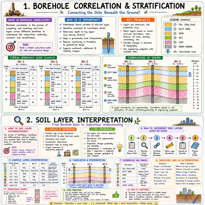
Values from these correlations are estimates, not test results. State the equation ID and source when one is used, confirm the soil or rock is within its range, and calibrate against site testing before design.
The correlations below are used or referenced in this chapter. Each is a statistical fit to a particular data set, so a value from one is an estimate: it applies only within the materials and ranges stated, carries the scatter of the original data, and must be confirmed by site-specific testing or calibration before it is relied on for design.
When an equation is used, note it with the result: give the equation ID and source, state that the soil or rock is within its range of applicability, mark the value as correlated (not tested), and record the limitation that governs. The Empirical Equations & Correlations reference has every entry with its full references.
Variables. Nm = field blow count; ERm = measured hammer energy ratio (%); CB = borehole diameter (1.0 for 65–115 mm, 1.05 for 150 mm, 1.15 for 200 mm); CS = sampler (1.0 standard, 1.1–1.3 liner-less); CR = rod length (0.75 <3 m; 0.8 3–4 m; 0.85 4–6 m; 0.95 6–10 m; 1.0 >10 m)
Use. All soils tested by SPT (ASTM D1586). Normalizes blow count to 60% of theoretical free-fall energy, the basis for most U.S. correlations.
Limitations. CE ranges ~0.5–1.6 depending on hammer type; use measured energy (ASTM D4633) where available. Rod-length factor ranges differ between Skempton (1986) and Youd et al. (2001).
Source. Skempton 1986; Youd et al. 2001 · In this chapter: APPENDIX A — BOREHOLE LOG TEMPLATE · Full entry and references
Variables. De = equivalent core diameter (mm); Is = P/De2
Use. Hard, isotropic rock; quick strength index in field.
Limitations. K varies widely with rock type and anisotropy; calibrate with lab UCS. Unreliable in weak rock (σc < ~25 MPa).
Source. Broch & Franklin 1972; ISRM 1985 · In this chapter: APPENDIX A — BOREHOLE LOG TEMPLATE · Full entry and references
Variables. σ'v0 = vertical effective stress at test depth
Use. Cohesionless soils; normalizes to σ'v0 = 1 atm. Cap of 1.7 recommended by NCEER workshop.
Limitations. Not applicable to clays. Unreliable at σ'v0 > ~200 kPa (other CN forms preferred at depth).
Source. Liao & Whitman 1986; Youd et al. 2001 · Full entry and references
↗ Open printable laboratory results template (letter landscape)
benesch| ProjectExample Siding Extension — Embankment Widening | Benesch project no.000000.00 | Client railroad[Railroad] | Report date__/__/____ |
| Laboratory[Laboratory name] | Accreditation[e.g., AASHTO re:source; USACE] | Tested by[Name] | Reviewed by[Name], P.E. |
| Boring | Sample | Depth (ft) | USCS | Gradation (D6913 / D1140) | Atterberg limits (D4318) | w (%) | γd (pcf) | Gs | Tests / remarks | ||||
|---|---|---|---|---|---|---|---|---|---|---|---|---|---|
| Gravel % | Sand % | Fines % | LL | PL | PI | ||||||||
| B-1 | SS-1 | 2.5–4.0 | SM | 2 | 71 | 27 | NP | NP | NP | 12.4 | — | — | D2216, D6913 |
| B-1 | SS-3 | 7.5–9.0 | CL | 0 | 18 | 82 | 42 | 20 | 22 | 24.1 | — | — | D2216, D4318, D1140 |
| B-1 | ST-1 | 10.0–12.0 | CH | 0 | 8 | 92 | 68 | 28 | 40 | 38.5 | 78.2 | — | D2216, D4318, D7263 |
| B-3 | ST-1 | 18.0–20.0 | CH | 0 | 6 | 94 | 71 | 29 | 42 | 42.1 | 76.5 | 2.72 | D854, D2435 |
| Boring | Sample | Depth (ft) | Test (ASTM) | Undrained | Effective stress | Consolidation (D2435) | Remarks | ||||||
|---|---|---|---|---|---|---|---|---|---|---|---|---|---|
| su (tsf) | εf (%) | c′ (psf) | φ′ (°) | Cc | Cr | σ′p (tsf) | cv (ft²/day) | Cα | |||||
| B-1 | ST-1 | 10.0–12.0 | D2850 (UU) | 0.24 | — | — | — | — | — | — | — | — | σ3 = 0.5 tsf |
| B-3 | ST-1 | 18.0–20.0 | D2435 | — | — | — | — | 0.59 | 0.14 | 1.50 | 0.15 | — | Casagrande σ′p |
| B-6 | ST-1 | 12.0–14.0 | D4767 (CU) | — | — | 200 | 31 | — | — | — | — | — | 3-point, with pore pressure |
| Source / location | Material | Test (ASTM) | Moisture–density | Bearing / stiffness | Remarks | ||||
|---|---|---|---|---|---|---|---|---|---|
| γd,max (pcf) | wopt (%) | Effort | Soaked CBR (%) | Swell (%) | Mr (psi) | ||||
| Borrow-1 | CL fill | D1557 | 118.2 | 14.0 | Modified | 24.3 | — | — | CBR at 95% RC, 96-hr soak (D1883) |
| Borrow-2 | SM fill | D1557 | 126.5 | 10.5 | Modified | 51.8 | — | — | CBR at 95% RC, 96-hr soak (D1883) |
| TP-3 subgrade | CL natural | D1557 | 116.8 | 15.2 | Modified | 12.6 | — | 4,200 | Mr at 95% RC (AASHTO T 307) |
| Tested by / date | Laboratory manager / date | Reviewed by (P.E.) / date | QC duplicate check (10%) |
Reference graphics

No additional content.
Twort and Rees’ chapter on bills of quantities is essentially a list of the measurement-and-payment wording that leads to claims. The points that bear on geotechnical work:
For railroad work: Each GSP in this template should end with a measurement-and-payment paragraph that applies these lessons:
Spell out which item absorbs the work of handling material during short track windows, such as stockpiling and re-handling, so that it does not become an extra.
Source: Twort, A. C., and Rees, J. G. (2004). Civil Engineering Project Management, 4th ed. Oxford: Elsevier Butterworth-Heinemann, pp. 182–186, 189–194. Summarized and paraphrased. Full reference under Supplemental Sources.
The ASCE guide lists recurring specification defects drawn from Committee surveys:
Its writing rules:
Appendix F of the guide classifies actual problem wording:
The Appendix G checklist is a quick review tool. It asks whether related sections are listed and duplication removed; whether references are current, available in the field and have their options selected; who tests, by what method and in what report format; and who measures, by what method, and whether payment is tied to the measured quantity.
For railroad work: GSP drafts should be checked against Appendix F before issue. For example, “Compaction tests shall be taken at locations selected by the Engineer” can be rewritten as “The Engineer will test in-place density at a minimum frequency of one test per [__] CY per lift, at locations selected by stratified random sampling”, with the frequency taken from the railroad’s standard. “Remove unsuitable material as directed” should become a defined criterion, such as a proof-roll deflection or classification trigger, plus an ordered-quantity pay item. Phrases such as “protect the track” should be replaced by citing the railroad’s fouling, flagging and monitoring requirements.
Source: ASCE Construction Institute Committee on Specifications (L. Eckersley, Chair) (2013). Preparation of Construction Specifications for Civil Projects. Reston, VA: American Society of Civil Engineers, pp. 3–4, 31–33, 54–60. Summarized and paraphrased. Full reference under Supplemental Sources.
Seeley describes the method-related charges introduced in CESMM. Many construction costs do not scale with the quantity of permanent work. Examples are bringing plant to site and removing it, site offices, temporary works and supervision. If these costs are spread through unit rates, any change in quantity overpays or underpays the contractor, and disputes follow. CESMM lets the bidder enter them separately, as one of two types:
Method-related charges are not remeasured. If the contractor priced a crane for 22 weeks and used it for 28, the price does not change automatically. If dewatering priced in the bid turns out to be unnecessary in a dry season, the sum is still paid, because the contractor carried the risk. The charges are adjusted only when an ordered variation changes the work or its duration. The contractor must describe each charge, including the resources and the parts of the work it relates to, but is not bound to use the method described. Seeley notes the risks: front-loaded charges, and vague descriptions that are hard to certify.
For railroad work: on railroad jobs, durations depend on track windows, and the windows are controlled by train traffic and the railroad’s operating decisions. A geotechnical special provision template therefore benefits from three kinds of item:
When a cancelled window then stretches the schedule, the extra cost lands on the time-related items, where it can be checked. It is not hidden in the cubic-yard rate. The template should also state which costs the railroad pays directly, such as flagging and work trains, so that bidders do not price them twice.
Source: Seeley, I. H. (1993). Civil Engineering Quantities, 5th ed. Basingstoke: The Macmillan Press, pp. 59–66. Summarized and paraphrased. Full reference under Supplemental Sources.
01.1 Scope. This section covers furnishing and placing all structural fill, embankment fill, and subgrade preparation within the limits shown on the contract drawings.
Reference graphics
Items from Profillidis that may be carried into project-specific special provisions for railway earthwork, subject to the engineer’s review:
After Profillidis (2014), §9.7.1, §9.12.2, §9.15.2. Full reference under Supplemental Sources.
Writing for owners, Levy (2010) explains how the earthwork specification allocates subsurface risk. Declaring the site unclassified makes the contractor responsible for removing whatever is found, including rock, shale, hardpan, old foundations, pavement and debris, at the bid price. That protects the owner, but bidders respond by carrying a contingency large enough to cover the worst case, and the owner pays it whether or not bad ground appears. Levy asks owners to consider whether it is cheaper to pay actual costs for legitimate unforeseen conditions than to buy that contingency up front.
He summarizes two claim types recognized in public contracting and generally accepted privately. A Type I claim requires that the contract documents indicated the subsurface condition, that the contractor read them reasonably and relied on them in its estimate, that actual conditions were materially different and reasonably unforeseen, and that the costs claimed relate only to the difference. A Type II claim requires showing what usual conditions would have been expected, what was actually found, that it differed materially from the known or usual, and that cost increased. Owners typically answer that conditions were not really different, should have been anticipated, or that the contractor used the wrong equipment or inexperienced operators. Levy cites agencies that use a 15% quantity rule as evidence of material difference, and an FHWA statement that federal-aid contracts carry a changed-conditions clause triggered when a major item changes by more than 25%. To support a claim the contractor should record the time and condition observed, the superintendent’s daily-log entry, photographs, statements from the operator or foreman, and the operation and exact location, and should notify the owner’s representative before the material is removed.
Levy also cautions that springs absent during a summer drilling program may reappear in spring, and that rock can lie between widely spaced borings.
For railroad work: In GSP-01, state whether excavation is classified or unclassified, and if classified, define rock and unsuitable material by measurable criteria and pay limits (paylines) below subgrade. Where undercut of soft subgrade beneath track is expected, carry it as a unit-price item with an estimated quantity rather than burying it in a lump sum. Include a notification clause that requires the contractor to stop and notify the railroad’s representative and the geotechnical engineer of record before removing material it considers different, so the condition can be observed and photographed in place.
Source: Levy, S. M. (2010). Construction Process Planning and Management: An Owner’s Guide to Successful Projects. Burlington, MA: Butterworth-Heinemann (Elsevier), pp. 21, 260–264. Summarized and paraphrased. Full reference under Supplemental Sources.
Seeley summarizes the earthwork rules of CESMM3 Class E. They are a useful checklist for writing the measurement-and-payment part of an earthwork special provision, because each rule closes off a common dispute:
For railroad work: for subgrade undercutting and embankment repair, the special provision should state the following. (1) The pay limits, as neat lines measured from a stated datum such as bottom of tie or design subgrade elevation. (2) A separate item for soft spots ordered below the planned undercut grade, so overruns are paid at a known rate. (3) A rock definition that uses the boring-log descriptions. (4) Whether fouled ballast is measured as excavation or as a separate removal-and-disposal item. (5) Whether stockpiling and rehandling is an item. Short track windows often force rehandling, so state it rather than leaving it to be argued.
Source: Seeley, I. H. (1993). Civil Engineering Quantities, 5th ed. Basingstoke: The Macmillan Press, pp. 87–89. Summarized and paraphrased. Full reference under Supplemental Sources.
01.3 Equipment. Compaction equipment to produce minimum modified Proctor density specified in Section 01.4. Compaction equipment shall not be operated within 5 ft of installed drainage pipe or within 3 ft of retaining wall or abutment face.
Reference graphics

Twort and Rees make a practical point about earthwork control: in situ density tests prove compliance after the fact. A sand-cone test takes hours, so it records past performance and cannot serve as real-time control. Real-time control comes from an inspector who watches every load as it is dumped, spread and compacted, has authority to reject material, and calls the resident engineer when in doubt. The cues they describe:
On moisture, they note that wet borrow and a wet formation may simply mean stopping work. Rolling the day’s surface smooth and to a fall sheds rain. Dry fill must be watered on the spread layer and mixed in, not just wetted on the surface.
On quantities, they stress bulking. Haul units have a fixed body volume. At a bulking factor of 1.2, each load carries about 83% of its body volume measured in place; at 1.35 it carries only about 74%. A disposal price based on the first figure but met with the second is about 12% short. They quote typical bulking of about 1.1–1.3 for granular and soft soils, about 1.4 for hard clays and 1.6–1.7 for broken rock. They also show how excavator bucket size is matched to truck return interval and loading cycle time, after allowing for bulking.
For railroad work: On embankment widening and subgrade replacement during a work window, there is no time to wait for density results before the next lift or before returning the track to service. Write the inspector’s authority to stop placement and reject loads into this GSP. Specify a test fill or roller-pattern trial at the start, and use proof-rolling observations as the lift-by-lift control, with nuclear or sand-cone density tests as the record. Size haul and disposal by loose volume. Undercut ballast and fouled subgrade spoil bulks significantly, and disposal along the right-of-way or off site is often the item that runs over.
Source: Twort, A. C., and Rees, J. G. (2004). Civil Engineering Project Management, 4th ed. Oxford: Elsevier Butterworth-Heinemann, pp. 228–231. Summarized and paraphrased. Full reference under Supplemental Sources.
Goldbloom treats Method of Measurement and Basis of Payment as the parts of an earthwork section that generate the most disputes. The quantity of earthwork is hard to predict, so most items are paid on measured actual quantities. A Fixed (Plan) quantity can be used where the geometry is fully defined. It is computed by average end areas from the engineer’s preconstruction cross sections and the plan dimensions, and it is marked “Fixed” in the bid schedule.
His recommended practices:
For railroad work: When adapting GSP-01 for subgrade rehabilitation or embankment repair, pay ordered undercut of unsuitable subgrade per CY, measured in place, with select fill and geosynthetics as separate items. Measure imported subballast and fill in place or at the source, not by truck count. If excavation support next to live track (shoring or soldier piles beside the fouling limit) is carried in a lump sum, its scope must be stated explicitly. Define the excavation classes so they match the boring logs. Whatever the specification says, the railroad’s contract form and pay-item list govern.
Source: Goldbloom, J. (1989). Engineering Construction Specifications: The Road to Better Quality, Lower Cost, Reduced Litigation. New York: Van Nostrand Reinhold, pp. 208–218. Summarized and paraphrased. Full reference under Supplemental Sources.
Sections on this page marked “After Profillidis (2014)” draw on the document below. Text is summarized or paraphrased; tables are transcribed or reproduced with their original source noted; figures and photos are reproduced from the cited document for internal reference use. Consult the original document before relying on a value for design. Blocks tagged “Project management” summarize methods, examples and figures from the project-management, estimating and construction-management books listed here, applied to railroad work; the closing “For railroad work” note in each block is added by the authors of this manual.
Authors: Daniel P. Colwell and Mario Ruel. This part was written and compiled by Daniel P. Colwell and Mario Ruel for Railway Ground Hazard Risk Management.
Technical content is drawn from the published sources below, and credit for that material belongs to their authors and publishers. Tables, equations and figures taken from a specific source are also cited where they appear.