
Geotechnical engineering libraryContact
 benesch
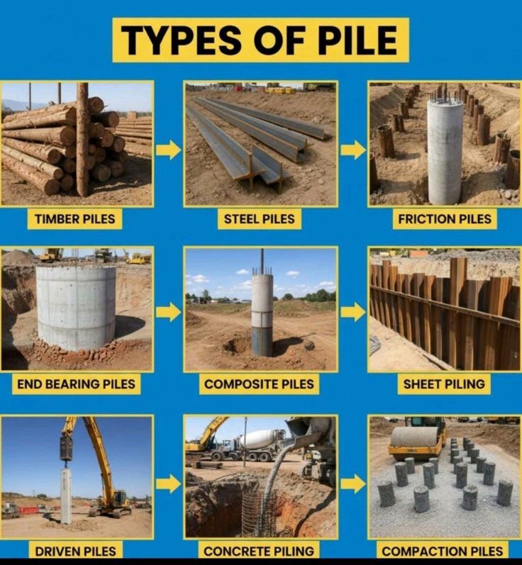
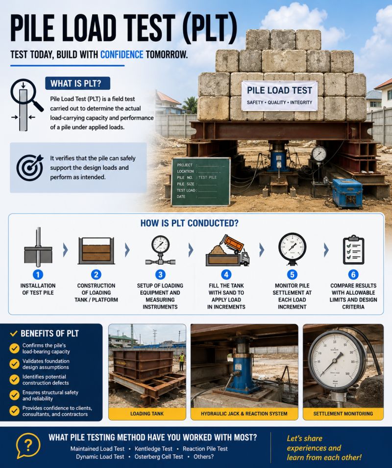
Supplementary graphics for GHRM Section 17.16.27 (Ground Improvement Technologies). The schematic summarizes how the technique works using the typical values documented on this page; the reference infographics are from the Named Graphics library. Click any graphic to enlarge.
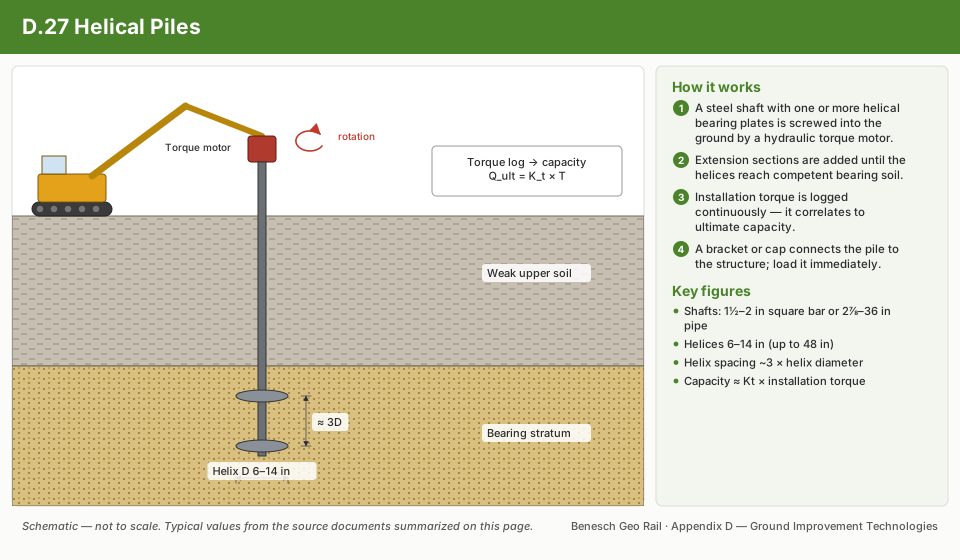
ECP's Torque Anchor™ screw piles use a solid square bar or tubular steel shaft with one or more helical plates welded on. Plate diameters run 6″–14″ at ⅜″ or ½″ thickness, spaced three plate diameters apart so each plate develops full bearing capacity, with a standard 3″ pitch (the shaft advances 3″ per revolution). They're well suited to combination tension/compression applications — metal buildings, canopies and monopole towers — and to retaining wall tiebacks, failed-foundation restoration, pipeline and pump equipment supports, elevated walkways, bridge abutments and electric utility structures.
| Shaft size | Configuration | Axial compression | Tension strength | Torsional strength |
|---|---|---|---|---|
| 1½″ sq. bar | Solid square bar | 40,000 lb | 60,000 lb | 5,500 ft-lb |
| 1¾″ sq. bar | Solid square bar | 60,000 lb | 100,000 lb | 9,000 ft-lb |
| 2⅞″ dia. tubular | 0.262″ wall | 100,000 lb | 100,000 lb | 9,500 ft-lb |
| 3½″ dia. tubular | 0.300″ wall | 115,000 lb | 120,000 lb | 13,000 ft-lb |
| 4½″ dia. tubular | 0.337″ wall | 160,000 lb | 140,000 lb | 21,000 ft-lb |
Torsional ratings assume homogeneous soil; obstructions can spike installation torque and fracture couplings, so select a product with margin above the expected installation torque.
Bearing capacity — the load a pile can carry without objectionable settlement — depends on soil type and properties, ground/surface water conditions, the pile's configuration (shaft size and type, helix diameter and count), depth to bearing, installation angle, pile spacing, installation torque and the type of loading (tension, compression, alternating).
For clay-only soils (Nq = 0, Nc = 9), this simplifies to Equation 2: Pu = ΣAH(9c). For sand/gravel-only soils (Nc = 0), it simplifies to Equation 3: Pu = ΣAH(qNq). Soil overburden pressure q is the dry soil density times layer thickness above the water table (Equation 4), or density reduced by 62 lb/ft³ for buoyancy below it (Equation 5) — summed layer by layer from the surface to the midpoint between the top and bottom helical plates.
Soil strength values come from classification tables keyed to SPT blow count "N": for cohesive soils (clays), undrained shear strength "c" and unconfined compressive strength rise with consistency from very soft (N 0–2, c < 250 lb/ft²) to very hard (N > 48, c > 6,000 lb/ft²); for cohesionless soils (sands/gravels), friction angle "φ" and bearing factor "Nq" rise with density from very loose (N < 6, φ 26°–30°, Nq 12–18) to very dense (N > 40, φ > 50°, Nq > 300).
| Shaft | 6″ | 8″ | 10″ | 12″ | 14″ |
|---|---|---|---|---|---|
| 1½″ sq. bar | 0.181 | 0.333 | 0.530 | 0.770 | 1.053 |
| 1¾″ sq. bar | 0.175 | 0.328 | 0.524 | 0.764 | 1.048 |
| 2⅞″ tubular | 0.151 | 0.304 | 0.500 | 0.740 | 1.024 |
| 3½″ tubular | 0.130 | 0.282 | 0.478 | 0.719 | 1.002 |
| 4½″ tubular | — | 0.239 | 0.435 | 0.675 | 0.959 |
Preventing "punch through": when competent soil overlies a weaker layer, keep the lowest helical plate at least 5× its diameter above the weak stratum so the pile doesn't punch through it once fully loaded.
Chance defines a shallow anchor as one whose top helix sits within 3 helix diameters of the surface, and a deep anchor as 5 diameters or more. A deep anchor is always preferred where possible: it reaches higher ultimate capacity, and if it does fail, it creeps rather than pulling out suddenly.
Two theories exist for multi-helix capacity. The bearing-plus-cylindrical-shear method treats the anchor as failing along a cylinder of soil connecting the top and bottom helix, plus bearing at the end. The bearing capacity method simply sums the individual bearing capacity of each helix. Chance's view: at close helix spacing (within ~6″) the cylindrical-shear theory controls; at wide spacing (~10 ft) individual bearing controls; the two converge around the industry-standard 3-diameter spacing, which is why Chance designs to the bearing capacity method.
As with the ECP method, whichever of the c-term or q-term isn't relevant for a given soil (clay vs. sand) is set to zero. Chance recommends field testing to confirm predicted capacities in all cases.
Installation torque has long been used as a field proxy for ultimate capacity: Qu = Kt × T, where T is the average installation torque and Kt is an empirical torque factor (Chance uses Kt = 10 for SS-series anchors, in tension or compression).
For underpinning applications, Chance's sample calculation also checks bending and buckling using the Cummings method (as cited by Terzaghi, 1943): solve for the number of half sine waves (m) the pile would form under lateral soil reaction, then check the critical buckling load against the applied load, and separately check eccentric loading against the shaft's rated bending capacity. A worked example (8″ wall, 6-kip load per pier, clayey sand, water table at 20 ft) selects a 10″ helix on a 1½″ × 12-ft square shaft, with buckling capacity (78,334 lb) and bending capacity (2.5× safety factor) both comfortably exceeding the 6,000 lb applied load.
| Helix size | Area (in²) |
|---|---|
| 6″ | 26.7 |
| 8″ | 48.4 |
| 10″ | 76.4 |
| 12″ | 111.0 |
| 14″ | 151.0 |
| Pier family | Max tensile | Max compressive | Max bracket capacity |
|---|---|---|---|
| 1½SS | 70 kips | 70 kips | 40 kips |
| 1¾SS | 100 kips | 100 kips | 60 kips |
| HS | 100 kips | 100 kips | 60 kips |
The source bulletin also includes installation-torque-vs-SPT-N reference charts (10″ helix, in sand above and below the water table, and in clay) used to sanity-check field torque readings against expected soil strength.
Before specifying a repair, find and address the actual cause of foundation distress ("the disease") — not just the visible cracking or settlement ("the symptoms"). Common causes fall into three groups:
| Steel resistance piers (end-bearing) | Helical screw piles (soil-bearing) |
|---|---|
| Bear on rock or another verified firm stratum — not the soil | Capacity comes directly from the surrounding soil |
| Soil testing helpful, but not required | Soil testing highly recommended |
| 100% of piers field-load-tested during installation | Not ideal where rock is near-surface or debris is buried |
| Quick, portable, all-weather, little/no vibration or "down drag," immediate loading | Same install advantages, plus minimal site disturbance and reusability in temporary work |
| Selection driven by settled structure weight, footing strength, product capacity, spacing, safety factor | Weaker soils need larger-diameter plates; denser soils need smaller ones |
Both approaches use the same underlying capacity equation, Pu = ΣAH(cNc + qNq), and the same torque-capacity relationship, Pu = k × T, with k = 9–10 for square-bar shafts and 6–9 for tubular shafts.
Break the structure into its component loads: roof framing and roofing, ceiling and insulation, exterior covering, wall and floor framing/covering/insulation/flooring, stem wall/slab/flooring, live loads and soil loads.
| Footing | Condition | Spacing |
|---|---|---|
| 8″×16″ spread footing, up to 2,000 lb/lf | 3½″ frame wall | 3½ ft O.C. |
| 24″ cast concrete stem wall | 8½ ft O.C. | |
| 20″ monolithic turndown | 8 ft O.C. | |
| 12″×24″ spread footing, up to 5,000 lb/lf | 12″ stem wall | 7 ft O.C. |
| 18″ stem wall | 8½ ft O.C. | |
| 24″ monolithic turndown | 5¾ ft O.C. |
Also worth confirming on every job: unsupported column height, and load-test acceptance criteria — a net deflection under 1″ at full load, with at least ½″ rebound, is generally considered acceptable.
HPS uses "screw anchor" for piles loaded in tension and "helical pile" for piles loaded in compression, though the hardware and design logic are the same either way. Pipe sizes run from 2⅞″ up to 12¾″ O.D. as standard (larger custom shafts exist), with helix diameters from 6″ to over 60″, spaced at roughly 3 diameters apart. Length is generally limited by the installation equipment's reach (often 20 ft or less per section), with additional lengths bolted or welded on to reach deeper.
History: screw piles date to an 1838 lighthouse and Eugenius Birch's 1863 Brighton West Pier (still standing, 140+ years later) — both installed by hand at roughly 10 ft/hour. Hydraulic torque motors, available from the 1960s on, made installation practical at scale; utilities were early large-scale adopters, using screw piles as tension tie-downs for transmission towers and guy wires.
| Application | Why helical piles fit |
|---|---|
| New construction foundations | Pile terminates in a pier cap embedded in the footing or grade beam; fast, economical |
| Foundation repair | HPS's Dura-Lift bracket system screws in alongside an existing foundation and can lift it back level |
| Oil & gas facilities | Rugged and low-maintenance under pump-jacks, compressor stations, tanks, flare stacks and skid buildings; resists vibration/cyclical loading |
| Temporary & modular buildings | Removable, reusable, no cure time — the structure can be welded and loaded immediately after install |
| General foundations | Handles static, alternating and vibratory loads, and high-overturning-moment structures like communication towers |
| Slope & bank stabilization | Installed near-horizontally into stable soil below a failure plane, then tied to a retaining structure |
| Street light bases | Custom cap/shaft/helix sizing per pole; quick, low-disturbance, reusable |
Soil capacity is what ultimately limits a helical pile, so the handbook opens with the basics: cohesive soils (clays, internal friction φ ≈ 0) behave rigidly — stiff clay acts almost like rock, soft clay behaves more like putty — while cohesionless soils (sands/gravels, φ > 0) act more like independent particles that reorganize under stress. As a pile advances through layered soil, installation torque rises and falls with each layer's strength, which is why continuous torque monitoring doubles as a real-time soil profile during installation.
Under tension in wet or saturated clay, a suction effect briefly resists upward pull as a low-pressure zone forms beneath the helix. Installation also compacts a zone of soil immediately around the shaft, which increases both bearing resistance and shaft friction (adhesion) once the pile is loaded.
| Cohesionless soil | Relative density | SPT N | Friction angle φ |
|---|---|---|---|
| Very loose | < 0.2 | < 4 | < 30° |
| Loose | 0.2–0.4 | 4–10 | 30°–35° |
| Compact | 0.4–0.6 | 10–30 | 35°–40° |
| Dense | 0.6–0.8 | 30–50 | 40°–45° |
| Very dense | > 0.8 | > 50 | > 45° |
| Cohesive soil | Undrained shear strength |
|---|---|
| Very soft | < 250 psf |
| Soft | 250–520 psf |
| Firm | 520–1,045 psf |
| Stiff | 1,045–2,090 psf |
| Very stiff | 2,090–4,180 psf |
| Hard | > 6,265 psf |
The handbook is explicit that these figures are representational, not a substitute for an actual geotechnical soil report.
For a multi-helix pile, total resistance combines cylindrical shear along the soil between the top and bottom helix, bearing at the end helix, and (for deeper piles) shaft friction. For a single-helix pile, there's no cylinder to shear, so resistance comes only from bearing plus shaft friction.
Uplift in cohesive soil follows the same logic with an uplift bearing factor Nu = 1.2(H/D), capped at 9. In cohesionless soil, the Mitsch & Clemence (1985) method applies instead, with bearing factor Nq = eπtanφtan²(45°+φ/2) — ranging from Nq=1 at φ=0° up to Nq=115 at φ=44°. Uplift behavior in sand splits into a shallow and a deep failure mode depending on the embedment ratio H/D relative to a critical value that itself depends on friction angle (from (H/D)cr≈2.5 at φ=20° up to ≈11 at φ=48°).
Minimum recommended safety factor is 2.0 in all cases, and HPS recommends an engineer design every project, with load testing wherever project data allows it.
Part 3, lateral resistance: a laterally loaded pile can fail three ways — the soil's capacity is exceeded, bending stress in the pile exceeds material limits, or deflection exceeds what the structure can tolerate. All three need checking. The handbook uses the "All Pile" method, first classifying the pile as behaving as a short rigid member or a long flexible one via the stiffness factors R (constant soil modulus) or T (linearly increasing modulus, more typical for normally consolidated clay and granular soils), then reading ultimate lateral resistance and deflection off charts built for cohesive and cohesionless soils.
Part 4, moments & deflections (CFEM 1992): models the soil as a series of horizontal springs (the "coefficient of subgrade reaction," ks), which for cohesionless soil scales with depth (ks = nh(z/d)) and for cohesive soil scales with undrained strength (ks = 67Cu/d). From the relative stiffness T, moment and deflection at any depth follow from coefficient charts.
Part 5, buckling: helical piles are long and slender, so extreme compressive loading can, in rare cases, cause the shaft to buckle — either folding near the surface where soil is weak, or bending under lateral load like any slender column. The handbook applies the Poulos & Davis (1980) method: treat the embedded pile as an equivalent fixed-base freestanding column of length Le (depth to the point of fixity, zf = 1.4R or 1.8T depending on soil type), then check the critical buckling load against the applied load using standard column formulas for free- or fixed-headed conditions.
HPS has manufactured multi-helix piles for tieback use since 1977, mainly for electric utility and oil & gas retaining structures, with use in retaining-wall tiebacks continuing to grow. Compared with a grouted anchor, a helical pile bears mechanically on undisturbed soil rather than relying on friction between soil and grout in an open hole — so there's no hole collapse risk, no casing cost, and testing/loading can happen immediately instead of waiting for grout to cure.
Tieback placement depends on wall backfill height and where the wall is bulging or cracking most; a rule of thumb calls for at least 6× the largest helix diameter of soil cover above the pile. The design method itself depends on the spacing-to-diameter ratio (S/D): at S/D ≥ 3, HPS testing supports treating each helix as behaving independently (the individual plate method); otherwise, the cylindrical shear method from Part 2 applies.
Shaft sizing balances axial load, tension load, lateral load, overturning moment, torque considerations, installation equipment and soil conditions. Common pipe shafts range from 2⅞″ (max torque ~8,000 ft-lb) up to 12¾″ (90,000+ ft-lb); helix diameters from 6″ to 48″ are matched to shaft size by a compatibility chart in the handbook.
Other project-specific factors — seismic considerations, soil chemistry and similar — may also come into play.
Governing standards referenced include the Canadian Foundation Engineering Manual, the Alberta Building Code, ASTM A252 (welded and seamless steel pipe piles), CSA G40.21 (structural steel), CSA W47.1/W59 (welding certification and practice), ASTM A153/CSA G164 (hot-dip galvanizing), and ASTM D1143/D3689/D3966 for compression, tension and lateral pile load testing respectively. Helical plate is minimum ASTM A36 or CSA G40.21 44W steel; pipe up to 3½″ meets ASTM structural-grade requirements (70 ksi min. yield / 85 ksi min. tensile), while 4½″+ pipe steps up to 90 ksi / 105 ksi. All welding is Canadian Welding Bureau –certified to CSA W47.1/W59.1.
Galvanizing: hot-dip zinc coating has a 150+ year track record and performs well across a soil/water pH range of 4.0–12.5. At a conservative 200µm coating thickness, expected service life is 50–100 years; HPS piles typically measure 300–400µm, which can roughly double that. Even after the zinc is fully consumed, residual zinc in the soil continues to reduce corrosion of the underlying steel. Where extra protection is warranted, cathodic protection is the other main option — either an impressed-current system or a sacrificial anode, relying on the fact that zinc is anodic to steel and so corrodes preferentially.
Key sources cited throughout the handbook, for anyone who wants to go deeper on the underlying theory: