
Geotechnical engineering libraryContact
 benesch
Primary Source: USACE EM 1110-1-1804, Geotechnical Investigations, 1 January 2001; AREMA Manual for Railway Engineering (MRE), Chapter 1 — Roadway and Ballast; client-specific railroad engineering standards as cited.
Apps on dirtbert.com that support this chapter. Each one runs in a web browser on a desktop or a phone, with nothing to install. How to use the apps (I.3). Tools marked TOOLS open in the Geotechnical Analysis Suite (Benesch sign-in); the orange card below lists each one by section.
NANCY pages ask you to accept the Use and Disclaimers once in each browser. MINA is a monitoring aid and is not for operational dispatch decisions.
Calculators and workbook tools from the Benesch Geotechnical Analysis Suite that support this chapter: 1 interactive calculator and 5 workbook guides. Each one is also placed inside the section it supports, in an orange tools strip.
| ST | Vertical Induced Pressures (Influence Factors)Used in 5.5 Boring Depth Planning — Criteria and Equations (English Units) | Calculator ▸ | Guide |
| PM | Proposal ChecklistUsed in 5.1 Background — Why Planning is a Billable Deliverable | guide only | Guide |
| PM | Cookbook ChecklistUsed in 5.4 Boring Location Planning — Criteria by Project Type | guide only | Guide |
| PM | Budget TrackingUsed in 5.1 Background — Why Planning is a Billable Deliverable | guide only | Guide |
| PM | Project Book Data SheetUsed in 5.4 Boring Location Planning — Criteria by Project Type | guide only | Guide |
| FF | One Call Utility ChecklistUsed in 5.4 Boring Location Planning — Criteria by Project Type | guide only | Guide |
Tools open on dirtbert.com and need the Benesch sign-in. Drafts pending Benesch final review, not for use in design.
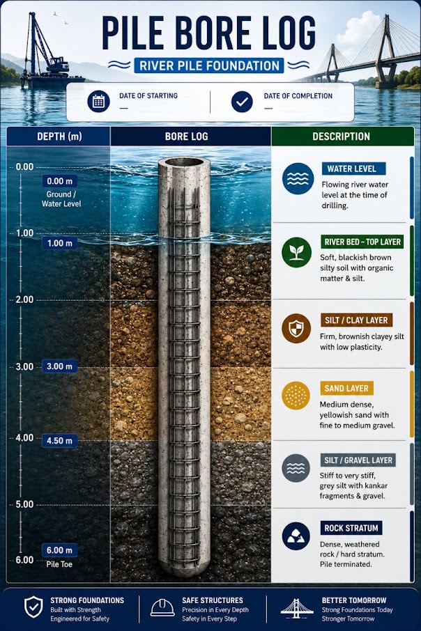
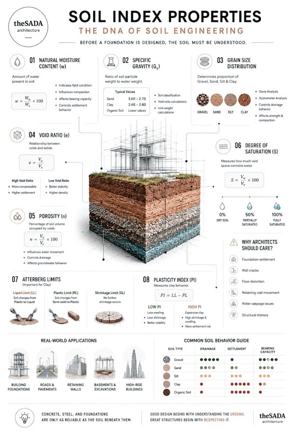
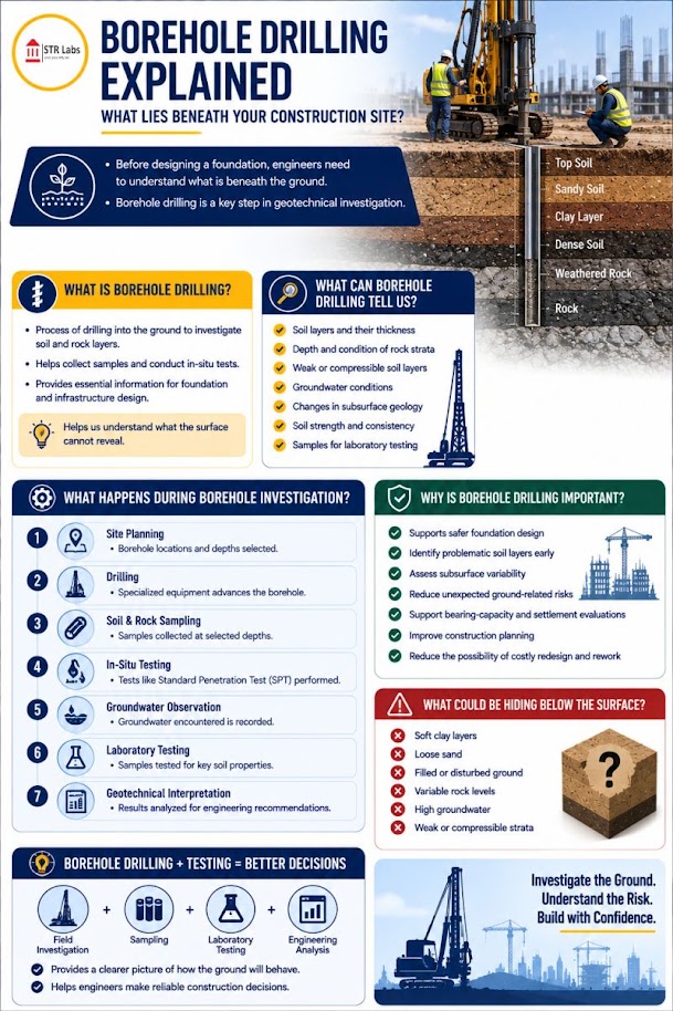
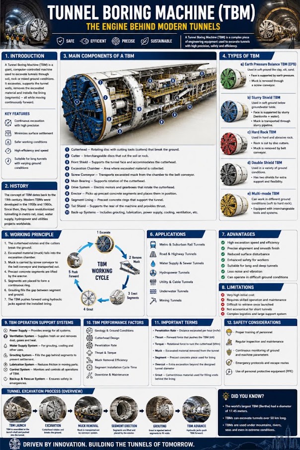
General topic illustrations from Benesch's shared geotechnical graphics library, related to this chapter's subject matter — not the numbered figures called out in the text above. Click any image to view it full size.
A well-planned geotechnical investigation is the foundation of every successful railroad engineering project. Planning errors — insufficient boring depths, wrong spacing, missing laboratory tests — cannot be corrected during analysis; they produce reports that fail engineering review, delay project schedules, and increase total project cost. This chapter establishes the systematic planning process we apply on every railroad geotechnical program, from the first desktop review through final boring layout approval. Key outputs of the planning phase are: a boring location plan dimensioned in feet and referenced to railroad mileposts, a boring depth matrix derived from stress influence calculations in English units, a laboratory testing assignment sheet linked to the specific design questions the investigation must answer, and a project-specific health and safety plan that satisfies the host railroad's Right-of-Way Protection (RWP) requirements.
Railroad client references: AREMA MRE Ch. 1 §1.4 (subgrade requirements); CSXT Engineering Standard for Geotechnical Investigations; NSR Engineering Standards Manual (NSR ESM) §3.2; UPRR Engineering Instruction Manual (UPRR EIM) §GT-100; BNSF Engineering Instructions (BNSF EI) — Geotechnical; CPKC Track Standards §Geo; Amtrak Engineering Standards — Geotechnical; CN Engineering Standards (CN ES) — Geotechnical; G&W Engineering Bulletins — Subsurface Investigations.
The correlations below are used or referenced in this chapter. Each is a statistical fit to a particular data set, so a value from one is an estimate: it applies only within the materials and ranges stated, carries the scatter of the original data, and must be confirmed by site-specific testing or calibration before it is relied on for design.
When an equation is used, note it with the result: give the equation ID and source, state that the soil or rock is within its range of applicability, mark the value as correlated (not tested), and record the limitation that governs. The Empirical Equations & Correlations reference has every entry with its full references.
Variables. Nm = field blow count; ERm = measured hammer energy ratio (%); CB = borehole diameter (1.0 for 65–115 mm, 1.05 for 150 mm, 1.15 for 200 mm); CS = sampler (1.0 standard, 1.1–1.3 liner-less); CR = rod length (0.75 <3 m; 0.8 3–4 m; 0.85 4–6 m; 0.95 6–10 m; 1.0 >10 m)
Use. All soils tested by SPT (ASTM D1586). Normalizes blow count to 60% of theoretical free-fall energy, the basis for most U.S. correlations.
Limitations. CE ranges ~0.5–1.6 depending on hammer type; use measured energy (ASTM D4633) where available. Rod-length factor ranges differ between Skempton (1986) and Youd et al. (2001).
Source. Skempton 1986; Youd et al. 2001 · In this chapter: 5.8 · Full entry and references
Variables. De = equivalent core diameter (mm); Is = P/De2
Use. Hard, isotropic rock; quick strength index in field.
Limitations. K varies widely with rock type and anisotropy; calibrate with lab UCS. Unreliable in weak rock (σc < ~25 MPa).
Source. Broch & Franklin 1972; ISRM 1985 · In this chapter: 5.7, 5.13 · Full entry and references
Variables. σ'v0 = vertical effective stress at test depth
Use. Cohesionless soils; normalizes to σ'v0 = 1 atm. Cap of 1.7 recommended by NCEER workshop.
Limitations. Not applicable to clays. Unreliable at σ'v0 > ~200 kPa (other CN forms preferred at depth).
Source. Liao & Whitman 1986; Youd et al. 2001 · Full entry and references
Variables. LL = liquid limit (%)
Use. Normally consolidated clays of low to moderate sensitivity.
Limitations. Reliability about ±30%. Not for organic or highly sensitive clays.
Source. Terzaghi & Peck 1967 · Full entry and references
Variables. R1 intact strength (0–15); R2 RQD (3–20); R3 discontinuity spacing (5–20); R4 discontinuity condition (0–30); R5 groundwater (0–15); Radj orientation adjustment (0 to −60 for slopes)
Use. Jointed rock masses; tunnels, foundations; slopes via SMR (RK-06).
Limitations. Mixed versions (1976 vs 1989) give different values; state which is used.
Source. Bieniawski 1989 · Full entry and references
Planning a geotechnical investigation for a railroad client is not overhead — it is a professional service that prevents costly scope errors and keeps the investigation aligned with the design question the railroad's engineering department needs answered. On railroad programs that operate under Professional Services Agreements (PSA), planning is typically the first deliverable under a task order: a written Investigation Plan or Boring Plan memorandum that the railroad project manager reviews and approves before field work begins.
USACE EM 1110-1-1804 §2-1 defines the objective of a geotechnical investigation as obtaining information that permits design of a safe and economic structure. This definition translates directly to railroad practice: every boring, every sample, and every laboratory test must be traceable to a specific design parameter needed by the railroad's engineering team.
The most common planning failure in railroad geotechnical work is designing the investigation around what is convenient to access rather than what the design requires. A convenient boring is one that can be reached with standard drill rig access from a paved road or an open field. But the critical foundation condition for a railroad bridge abutment, retaining wall, or track embankment is often in a location that requires a track window, specialty equipment, or an ROW access permit — not a convenient open-field location. We plan investigations around the design question first; we solve the access problem second.
Reference graphics
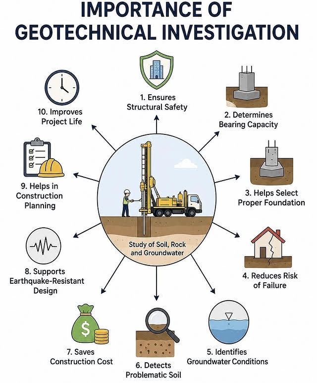
Table 5-S3. Site investigation cost as a percentage of project cost (Rowe, 1972, in Look, 2007)
| Type of work | % of capital cost | % of earthworks & foundation cost |
|---|---|---|
| Earth dams | 0.89–3.30 | 1.14–5.20 |
| Railways | 0.60–2.00 | 3.5 |
| Roads | 0.20–1.55 | 1.60–5.67 |
| Bridges | 0.12–0.50 | 0.26–1.30 |
| Embankments | 0.12–0.19 | 0.16–0.20 |
| Overall mean | 0.7 | 1.5 |
Railways sit near the top of the range. Look recommends budgeting no less than 0.2% of capital cost, notes that laboratory testing is typically only 10–20% of investigation cost, and warns against the competitive-bid trend of cutting lab testing and inferring design parameters from field classification alone. In Look’s relative risk ranking, rail embankments and railway bridges are rated higher-risk developments than road embankments and highway bridges.
Source: Look, B. G. (2007). Handbook of Geotechnical Investigation and Design Tables. Taylor & Francis
Case study: 5.14.1 No investigation: “the site across the road is the same” (Look 2023), in §5.14 Case Studies.
Miller argues that a project plan should be organized around deliverables rather than activities, because the client cares about what the project hands over, not the list of tasks performed. Deliverables are written as nouns. They are arranged in a product breakdown structure (PBS), the top component of the WBS, drawn either as an organization chart or as an indented outline. The single topmost deliverable is level zero; each lower level is produced by successive decomposition of the level above.
A complete PBS holds three kinds of deliverables:
The fourth level is usually enough detail to control the work. Go deeper where a deliverable is subcontracted (the subcontractor defines two further levels below it), where the deliverable is unfamiliar to the team, or where a team member is unknown to the manager. Miller rejects arbitrary rules such as “no activity longer than 40 hours”; each lowest-level deliverable should define one complete activity. His worked example decomposes a one-day recognition event for 400 employees through Events → Children’s Program → Rides → individual rides.
For railroad work: make level zero the thing the railroad is buying, for example “Geotechnical data report and repair recommendations, embankment at MP 112.4.” Level 1 legs might be Field Data, Laboratory Data, Analyses, Reports, Process Deliverables and Client Deliverables. Put the railroad’s obligations on the client leg: right-of-entry and track-access approval, track time and flagging or other roadway worker protection, utility and signal cable records, as-built drawings and the slow-order and maintenance history of the site. Group the safety plan, job-briefing plan, boring location plan, drilling subcontract and chain-of-custody procedure on the process leg. Because drilling is normally subcontracted, have the driller break the drilling deliverable into two more levels (mobilization, each boring log with its sample set, grouting records). A PBS of this kind also makes a clear scope exhibit for the proposal and shows the client exactly what each fee line produces.
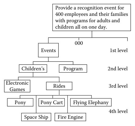
Source: Miller, D. P. (2009). Building a Project Work Breakdown Structure: Visualizing Objectives, Deliverables, Activities, and Schedules. ESI International Project Management Series. Boca Raton, FL: Auerbach Publications (CRC Press, Taylor & Francis Group), pp. 23–25, 31–33, 45–49. Summarized and paraphrased; figures reproduced for internal reference. Full reference under Supplemental Sources.
Oberlender frames every project as passing through owner’s study, preliminary engineering, detailed design, procurement and construction. His central argument, shown as two opposing curves, is that the ability to influence quality, cost and schedule is highest at the start and falls steadily, while the cost of implementing a change is lowest at the start and rises steeply once procurement and construction begin. Savings are made early, not at the start of construction.
From this he draws several working rules:
He also cites the Construction Industry Institute’s Project Definition Rating Index (PDRI): 70 scope elements, each rated 1 (complete) to 5 (poor), weighted to a maximum of 1,000 points. In the CII study, projects that scored below 200 performed significantly better than those that scored above 200.
For railroad work: The geotechnical investigation sits at the high-influence end of the curve. Boring locations, depths and lab assignments are fixed while the repair concept (undercut and blanket, shear key, wall, ground improvement or culvert replacement) is still open. Once a track window is booked and materials are ordered, changing direction costs track time as well as money. Before mobilizing a drill rig, confirm with the railroad’s project engineer the purpose of the work, the performance target (for example, removing a slow order or meeting a settlement tolerance), the access and work-window constraints, and the not-to-exceed budget. Record any assumptions in the scope letter so that a later change, such as adding a culvert crossing or extending the limits after a new slip, is visibly a change and is priced as one.
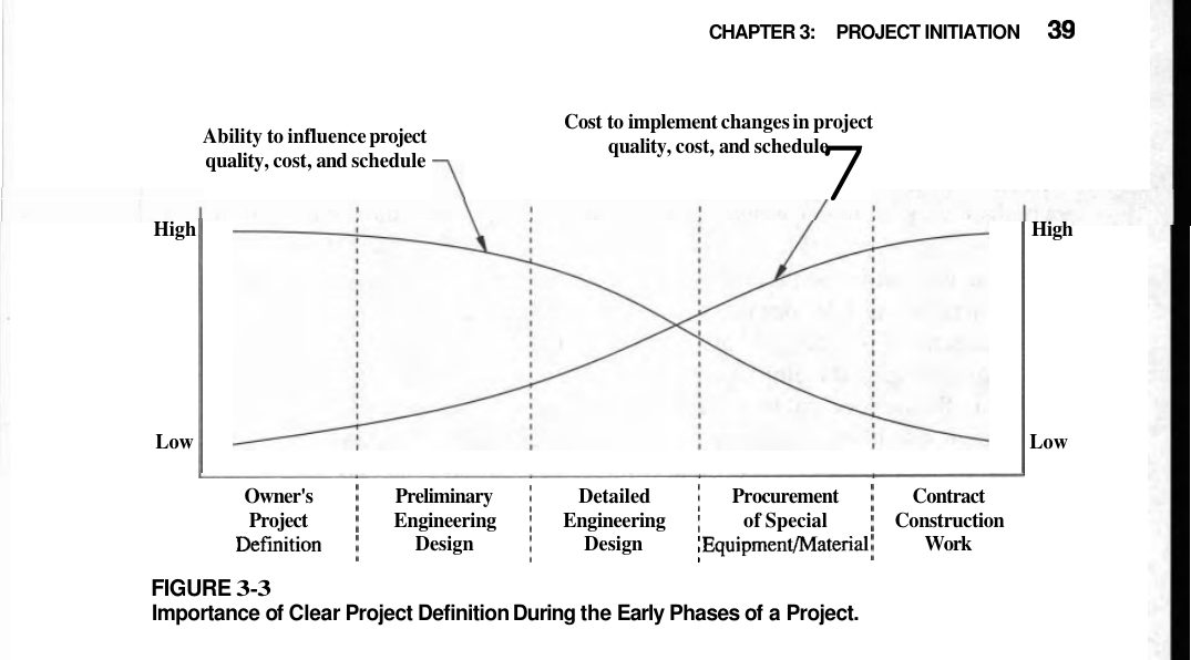
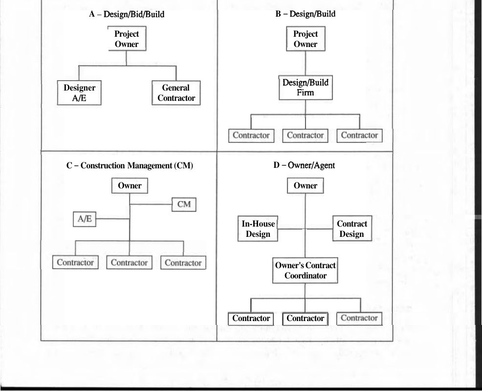
Source: Oberlender, G. D. (2000). Project Management for Engineering and Construction, 2nd ed. Boston: McGraw-Hill, pp. 33–41, 119–121. Summarized and paraphrased; figures reproduced for internal reference. Full reference under Supplemental Sources.
Cretu, Stewart and Berends describe four estimate levels (planning, scoping, design, and final/letting), each with its own purpose, method and expected accuracy. The accuracy range narrows as design matures, but it is not symmetrical: the upper end sits much farther above the baseline than the lower end sits below it, and the upper end moves toward the baseline faster as project-specific information is gained. The authors read this as evidence that economic and political pressures push early numbers down, and they warn reviewers to watch for it. They place reasonably firm project definition at roughly 30 percent design. Before that point the estimate range is driven mostly by scope uncertainty; after it, by unit-cost and market uncertainty plus discrete risk events.
Their illustration uses a project that ends up costing $100 million. Read from their chart, the plausible range at about 2 percent design runs from roughly $50 million to $300 million, tightens to about $70–150 million at 30 percent, and is close to $95–110 million at letting. In the same way, the “miscellaneous item allowance” that covers undefined scope typically falls from 30–50 percent at planning, to 20–30 percent at scoping, to 10–20 percent during design, and to zero at letting, when every item should be defined. The authors also call for a written basis of estimate (BOE) that records scope, exclusions, assumptions, data sources and the threats and opportunities known when the estimate was made. They urge reporting early estimates as ranges, because the first number given is the one everyone remembers.
For railroad work: On subgrade rehabilitation, slide repair and culvert replacement projects, the upper tail of the estimate is driven mainly by ground conditions: depth to competent material, soft or organic foundation soils, groundwater, and the extent of fouled ballast or a failed subgrade layer. That makes the investigation the main way to pull the upper end down before the railroad sets a capital budget. When scoping a program, show the client the current estimate range, identify which geotechnical unknowns control its upper end, and describe how the proposed borings, CPT soundings or GPR would narrow it. Record the geotechnical assumptions behind each estimate in a BOE-style note, such as an assumed undercut depth, assumed rock line or assumed drainage outfall, so that later changes can be traced to new subsurface data rather than read as estimating error.
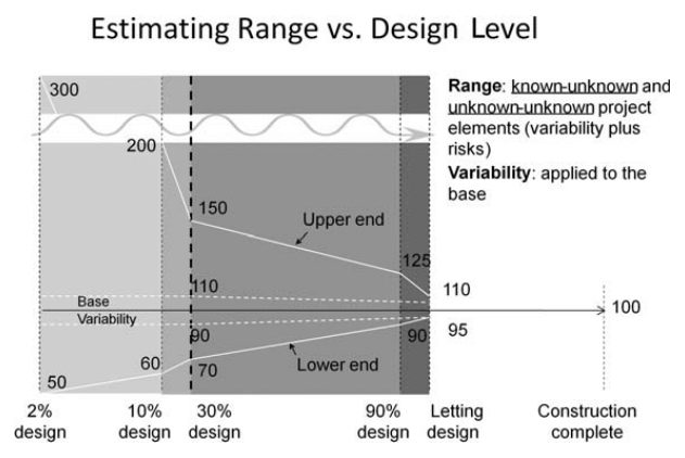
Source: Cretu, O., Stewart, R. and Berends, T. (2011). Risk Management for Design and Construction. Hoboken, NJ: John Wiley & Sons, pp. 18–25. Summarized and paraphrased; figures reproduced for internal reference. Full reference under Supplemental Sources.
Every railroad geotechnical investigation begins with a desktop review before a single boring is planned. The desktop review assembles all available prior subsurface and surface information for the project corridor and produces a preliminary geologic model that frames the entire investigation strategy.
Reference graphics
Existing boring data: Railroad clients maintain subsurface databases of varying quality. CSXT and UPRR maintain central engineering databases that may contain prior boring logs for the project corridor. NSR Engineering Services in Roanoke archives prior geotechnical reports and can provide boring logs for NSR network segments. BNSF Engineering in Fort Worth maintains a GIS-based boring database for capital projects. For G&W subsidiary networks, prior subsurface data is often sparse or held at the subsidiary level — contact the G&W corporate engineering group early to determine what is available.
Published geologic maps: USGS 7.5-minute quadrangle maps and state geologic surveys provide bedrock and surficial geology. The USGS National Geologic Map Database is the primary digital resource. Specific attention: karst terrain (Missouri, Indiana, Kentucky — CSXT, UPRR, CN corridors), residual soil from granitic gneiss (Virginia, North Carolina, Georgia — NSR, CSXT corridors), loess deposits (Mississippi Valley — UPRR, CN, BNSF corridors), expansive clay (Gulf Coast, Texas — UPRR, BNSF, CPKC corridors).
USDA Web Soil Survey: Provides surficial soil mapping at 1:24,000 scale. Useful for preliminary identification of potentially soft or problematic subgrades along new alignment corridors.
FEMA Flood Insurance Rate Maps (FIRM): Identify flood-prone zones and potential high-water conditions for bridge approaches, embankments, and drainage structures on all nine railroad clients' corridors.
Aerial photographs and satellite imagery: Historical aerial photograph archives (USGS EarthExplorer) reveal past land use, former fill areas, evidence of slope movement, and changes in drainage patterns that may not appear in current satellite imagery.
LiDAR digital elevation models: State and federal LiDAR datasets provide 1- to 2-ft contour resolution suitable for preliminary slope geometry characterization and drainage analysis. Most state DOTs and USGS provide free LiDAR downloads.
Prior geotechnical reports: Obtain all prior geotechnical reports for the project corridor, including reports prepared for adjacent projects on the same railroad. For NSR and CN, prior reports may reside in the railroad's internal engineering archive rather than with the geotechnical consultant.
Reference graphics
Change in track geometry under traffic comes from one of two sources: cumulative deformation of the ballast and subballast, or movement of the subgrade. Field observation combined with maintenance records at chronic spots tells the two apart. Frequent resurfacing at the same location, when it traces to the subgrade, points to low bearing capacity. Ask the client for:
Build up a district file of soil and geology maps that later projects can reuse. A deterioration rate that rises from one maintenance cycle to the next is a useful trigger for a substructure investigation.
After Selig & Waters (1994), chs. 4, 10 and 15. Full reference under Supplemental Sources.
The desktop review culminates in a written memorandum — typically 3 to 8 pages — that the railroad project manager can review before authorizing field work. The memorandum covers:
Yards, fueling facilities, former industrial spurs and sidings next to waste sites often put a geotechnical boring inside an environmental compliance or remediation footprint. Repetto (2003) groups these projects as waste disposal (landfills, lagoons, tailings), compliance at active facilities, and remediation at closed facilities; the containment systems used are liners, low-permeability covers and slurry-wall cut-offs. When the desktop review identifies one of these, the plan should:
Source: Repetto, P. C. (2003). “Geo-Environment,” Ch. 26 in The Civil Engineering Handbook, 2nd ed. CRC Press
Profillidis starts every geotechnical investigation with available documents (topographic, geologic and hydrogeologic maps, aerial photographs, historical investigation records) and a site reconnaissance, to understand the likely problems and to plan the main study. For new-line design he ties the investigation to the design stages:
| Stage | Mapping scale | Scope |
|---|---|---|
| Preliminary design | 1:50,000 or 1:25,000, aerial / satellite imagery | 2–4 possible routes; horizontal and longitudinal profiles; major structures, utilities and first cost estimate |
| Outline design | 1:5,000; cross-sections every 330 ft | 2–3 routes within a corridor 164 ft wide (flat terrain) to 1.2 mi or more (mountains); subgrade and drainage, bridges and tunnels, construction planning |
| Final design | 1:2,000–1:1,000 (difficult terrain); 1:1,000–1:500 (urban) | Balance of speed, curvature, gradient and soil-mechanics constraints; minimize future maintenance |
For existing lines built decades ago, he notes that a full analytical survey is usually not needed, but a general knowledge of the subgrade’s basic mechanical behavior is essential.
Figures · click to zoom
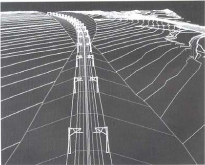
After Profillidis (2014), §9.2.2, §9.3, §14.13–14.14, Fig. 14.12. Full reference under Supplemental Sources.
Similar landforms are built the same way and contain similar materials. Identify the landform and you can predict the material and how it will behave. Almost all railway terrain has published geologic and soil mapping, and cross-referencing problem sites against it is a useful desktop habit.
Figures · click to zoom
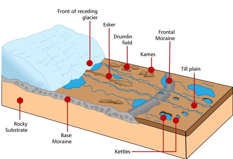
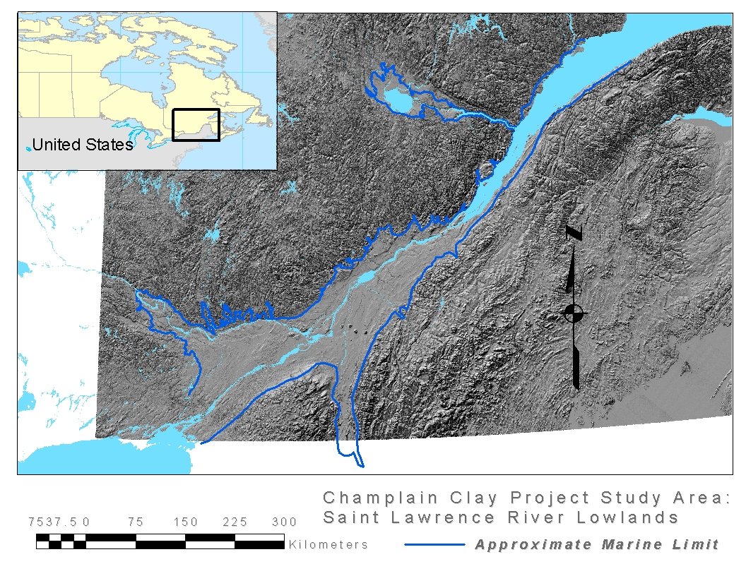
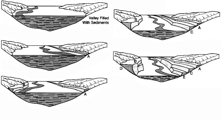
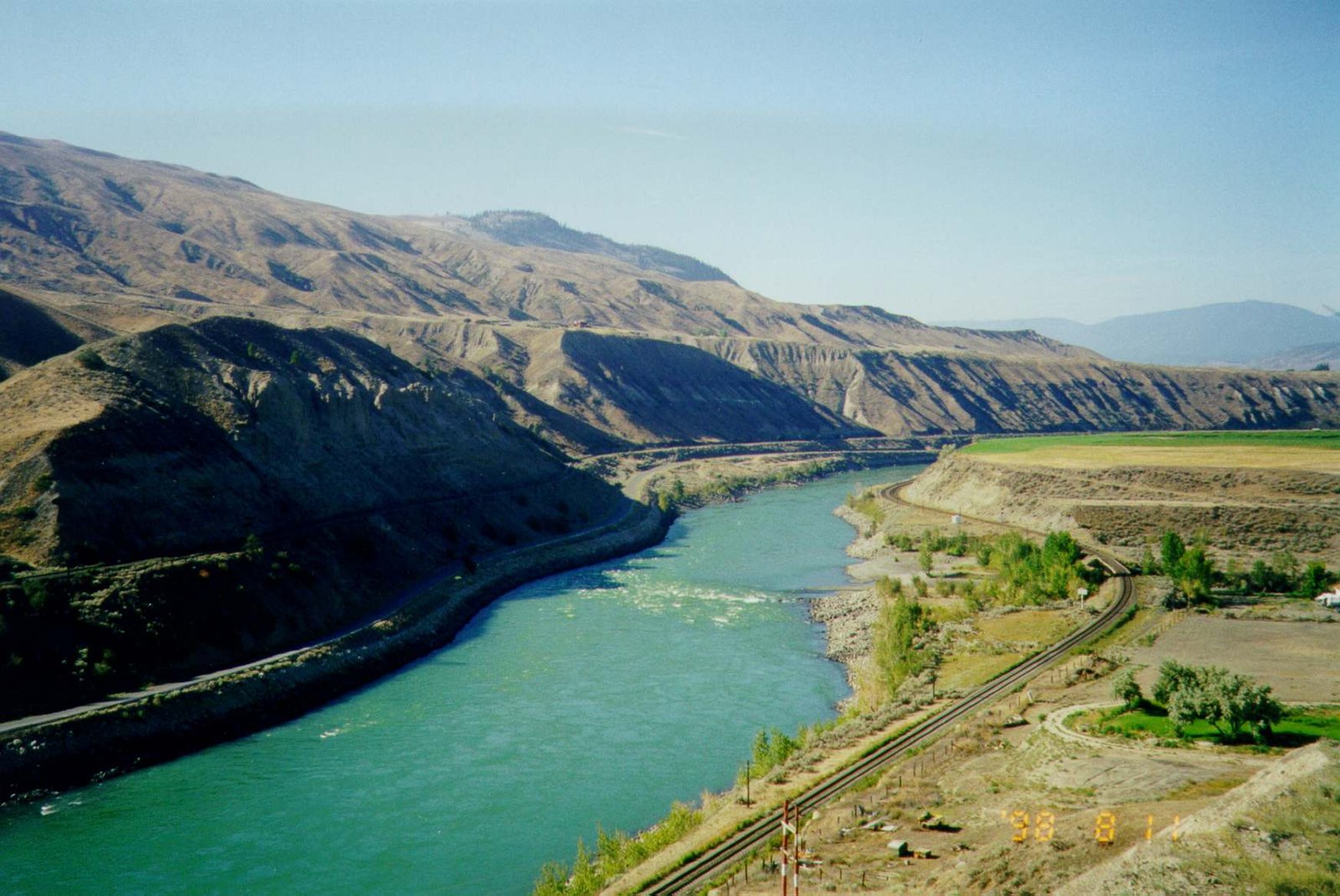
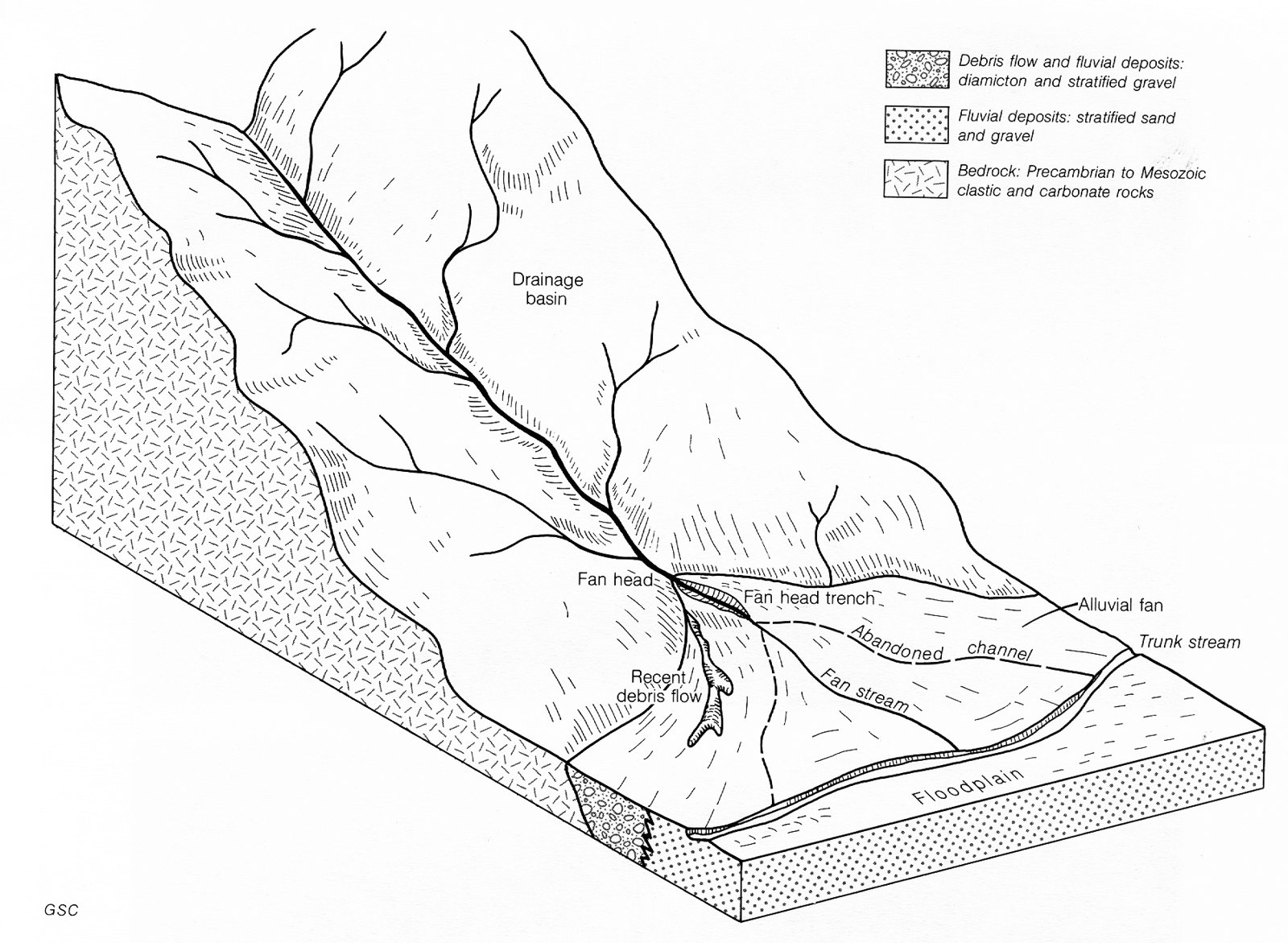
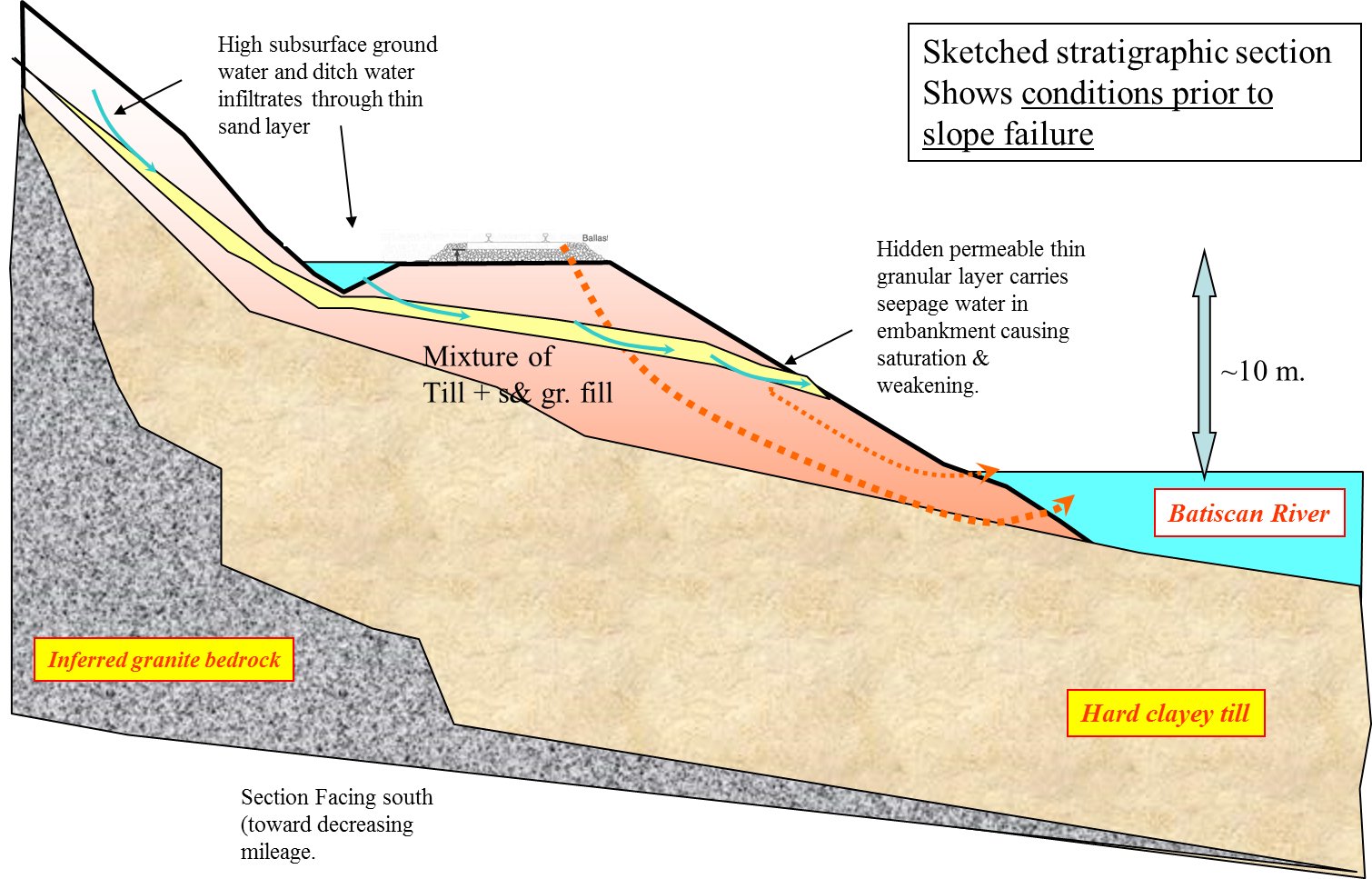
After Geotechnology for Railroaders Program, Module 2; §02–06. Full reference under Supplemental Sources.
Traffic type and volume drive the track structure, the number and length of yard and support tracks, and the terminal layout. Collect the traffic basis during the desktop review and have the client confirm it in writing. Only then set the investigation scope and the design loads. Cover both existing traffic and foreseeable growth, including surge or peak periods.
| Item | What to obtain | Why it matters |
|---|---|---|
| Traffic type | Commodities handled; car types and sizes; loading and unloading method; height and width of loads on open cars (flats, gondolas); special handling or restrictions, especially hazardous materials | Loading facility type, clearances, special containment |
| Traffic volume | Maximum cars of each type on site at one time, including empties; maximum cars of all types; longest train into or out of the site; maximum cars each loading facility handles in one cycle | Number and length of tracks, yard and terminal capacity |
| Wheel loads | Heaviest loaded car in common use on each track; heaviest locomotive (owner’s and serving railroad’s) | Design wheel load (Chapter 2, Table 2-S8) and subgrade stress |
| Locomotive tractive effort | Tractive effort curve, or locomotive weight and horsepower if no curve is available | Train size versus ruling grade and curvature |
| Sources | Client operating and transportation staff, shippers, the serving railroad, existing capacity studies | Traceable basis for the design |
After UFC 4-860-01FA (2004), ch. 2, §§1–3, 5 and 7. Adapted from military installation practice to railroad and industrial clients by Benesch. Full reference under Supplemental Sources.
Case study: 5.14.2 A buried creek the ground model missed: deep basement dewatering (Look 2023), in §5.14 Case Studies.
Before finalizing boring locations and depths, we confirm which standards govern the investigation. Railroad clients do not all use the same standards; mixing them up is a professional error that creates review problems and can require costly revisions.
AREMA MRE Chapter 1 — Roadway and Ballast is the common technical baseline for subgrade-related investigations on all nine railroad clients. AREMA MRE Chapter 1 §1.4 (Subgrade) requires that the stability of the roadbed subgrade be determined before specifying ballast and subballast thickness. AREMA MRE Chapter 8 — Structures governs foundation design for bridges, retaining walls, and culverts using Cooper E-80 design live load.
CSXT Engineering Standard for Geotechnical Investigations specifies CSXT-specific requirements for boring spacing on new sidings and embankment widening projects, minimum boring depth multipliers for embankments over soft ground, and CSXT's RWP and flagging requirements that must be reflected in the project-specific Health and Safety Plan.
NSR Engineering Standards Manual (NSR ESM) §3.2 specifies NSR's requirements for geotechnical investigation planning, including NSR's preferred boring log format, coordinate system requirements (Virginia State Plane, FIPS 4501), and NSR's requirement that the investigation plan be submitted to NSR Engineering Services for comment before field work begins.
UPRR Engineering Instruction Manual (UPRR EIM) §GT-100 governs UPRR's geotechnical investigation standards, including UPRR's requirements for investigation scope on new siding and yard projects and UPRR's flag and protect requirements for ROW access.
BNSF Engineering Instructions (BNSF EI) specify BNSF's investigation standards. For BNSF intermodal yards — a significant recurring project type — BNSF EI provides minimum boring spacing and depth requirements for crane rail foundation design under Cooper E-80 plus intermodal lift equipment loads.
Amtrak Engineering Standards — Geotechnical governs Amtrak NEC and other Amtrak corridor projects. Amtrak ES requires a higher level of investigation detail than most freight railroad standards, reflecting the Class 6 and Class 7 track geometry tolerances (¾ in. and ½ in. cross-level, respectively) that NEC operations must maintain.
CPKC Track Standards §Geo governs investigation requirements post-merger. Confirm current applicable standards with CPKC Engineering at project initiation; legacy CP and legacy KCS standards may apply to specific network segments pending harmonization.
CN Engineering Standards (CN ES) — Geotechnical govern CN investigation requirements in both US and Canadian operations. For Canadian operations, Transport Canada Railway Safety Act (TC RSA) regulatory requirements must also be reflected.
G&W Engineering Bulletins — Subsurface Investigations provide G&W corporate engineering guidance for subsidiary networks. G&W subsidiary networks vary significantly in track class, loading, and operating characteristics; the applicable FRA track class must be confirmed for each G&W subsidiary project.
Reference graphics
Pipeline and utility crossings are a frequent small task order, and the railroad’s occupancy specification — not the utility owner’s design standard — sets the investigation scope. CSXT’s Pipeline Occupancies specification (rev. 2018) requires:
Table 5-S1. CSXT live load on buried structures, Cooper E-80 including impact
| Cover (ft) | 2 | 3 | 4 | 5 | 6 | 8 | 10 | 12 | 16 | 20 | 25 | 30 |
|---|---|---|---|---|---|---|---|---|---|---|---|---|
| Load (psf) | 3,800 | 3,150 | 2,850 | 2,550 | 2,250 | 1,700 | 1,300 | 1,000 | 625 | 400 | 250 | 150 |
For lateral surcharge on sheet piling or pits beside the track, CSXT specifies a Boussinesq strip load 8.5 ft wide (tie length) with q = 80,000 / (8.5 × 5) = 1,882 psf per E-80 axle. Expect pushback on casings from pipeline owners: Miesner and Leffler explain that the industry has moved away from cased road and railroad crossings because the carrier must be electrically insulated from the casing to prevent galvanic corrosion, and shorted casings are a chronic corrosion problem. That is the reason owners ask for uncased crossings — which CSXT allows for gas lines only at 10 ft or more below base of rail.
Source: CSX Transportation (2018). Design and Construction Standard Specifications — Pipeline Occupancies. Office of VP–Engineering, Jacksonville, FL (rev. June 5, 2018) · Miesner, T. O. and Leffler, W. L. (2006). Oil and Gas Pipelines in Nontechnical Language. PennWell
Source: Norfolk Southern Corporation. Guidelines for Under Track Culverts
The following boring spacing criteria are consistent with AREMA MRE Chapter 1, USACE EM 1110-1-1804 Chapter 2, and the specific railroad client standards cited.
| Project Type | Minimum Borings | Typical Boring Spacing | Notes |
|---|---|---|---|
| New Mainline — Fill | 1 per 500 ft along centerline | 300–500 ft | Add borings at each drainage crossing, fill/cut transition |
| New Mainline — Cut | 1 per 300 ft along centerline | 200–300 ft | Add borings at slope crests and toes |
| New Siding (≤ 5,000 ft) | Minimum 3 borings | 1,500 ft typical | 1 at each end + 1 mid-siding; add at drainage crossings |
| New Siding (> 5,000 ft) | 1 per 2,500 ft minimum | 1,500–2,500 ft | Add borings at all structures |
| Track Extension | 1 per 1,000 ft | 500–1,000 ft | Governed by existing vs. new subgrade conditions |
| Bridge Abutment | 2 per abutment | N/A | Add 1–2 pier borings per intermediate pier |
| Retaining Wall | 1 per 100 ft | 50–100 ft | Denser spacing in variable ground |
| Intermodal Yard — Crane Rail | 1 per 200 ft along crane rail lines | 150–200 ft | Controlled by crane load concentration |
| Intermodal Yard — Pavement | 1 per 2 acres | N/A | Add borings at drainage structures |
| Slope Failure — Emergency | 3–5 targeted borings | N/A | Located at head scarp, mid-slope, toe |
| Subgrade Failure / Mud Boil | 2–4 borings | N/A | Straddle the failure zone |
Milepost referencing: All boring locations must be described in terms of railroad mileposts and offset from track centerline (in feet, left or right, looking in the direction of increasing milepost). GPS coordinates (NAD 83, decimal degrees or State Plane in feet) are required in addition to milepost references. Railroad mileposts are the primary location reference for all railroad engineering documents.
Reference graphics
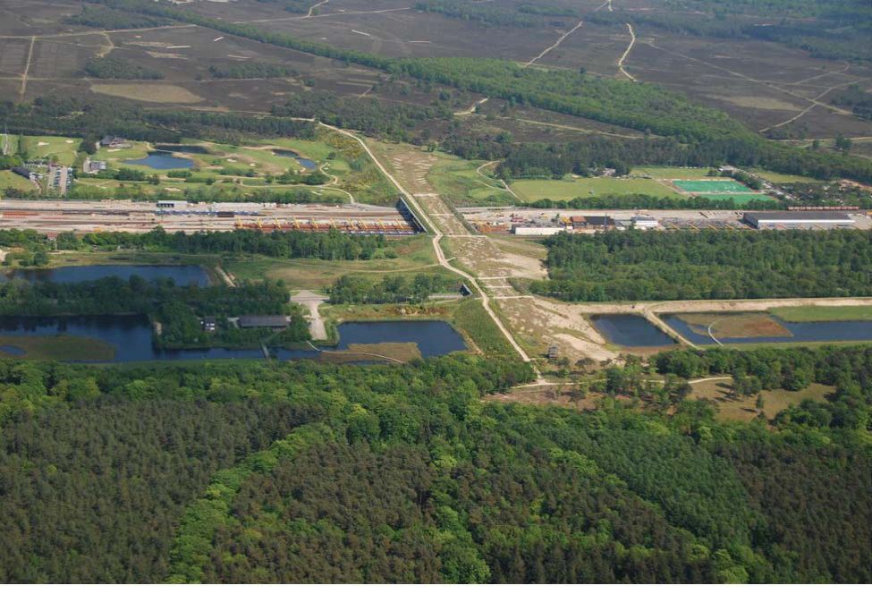
New alignments and major culvert or bridge replacements increasingly include wildlife passage as a permit condition. The FHWA Wildlife Crossing Structure Handbook gives recommended dimensions for eleven crossing types (overpasses, open-span bridges, large culverts, etc.); most overpasses are under 230–260 ft long, but landscape bridges spanning roads and a railway can be much longer. When a crossing structure is in the scope, add borings at both abutments/footings of the wildlife structure and at the approach fills, and confirm the clear-opening dimensions with the environmental permit before setting foundation boring depths.
Source: Clevenger, A. P. and Huijser, M. P. (2011). Wildlife Crossing Structure Handbook: Design and Evaluation in North America. FHWA-CFL/TD-11-003
No new line can be designed correctly or built economically unless the soils and hydrogeology along the route are known in detail. Profillidis lists what the investigation must establish:
Because investigation is costly, run it in stages: assemble existing information; reconnaissance (geologic and topographic maps, aerial photos, water and oil well logs, hydrologic data, state soil manuals); a preliminary site investigation with a few borings or test pits to establish stratification, soil types and groundwater; then the detailed investigation. The program should yield strength, deformation and hydraulic properties at the least cost. Techniques fall into geophysical (seismic, magnetic, gravimetric, resistivity), physical (borings, test pits), mechanical (pressuremeter, penetrometer, laboratory) and hydrogeological (piezometers) methods.
After Profillidis (2014), §9.2.1–9.2.4. Full reference under Supplemental Sources.
Before the track structure is designed, the investigation along the alignment should establish, at a minimum:
Add borings, laboratory testing and analysis at bridges and other special structures. AREMA Chapter 1, Part 1 gives the base recommendations, and the spacing in Table 5-1 applies. Where chemical stabilization is under consideration in a frost area, include frost-susceptibility and freeze–thaw durability testing in the laboratory program.
After UFC 4-860-01FA (2004), ch. 6, §8b and §8e. Full reference under Supplemental Sources.
Do not judge the trackbed from the surface. Clean ballast at the surface may be only one particle thick. Selig and Waters recommend the following, in order of effort:
Depth. Traffic stress is significant to about 16 ft below the tie, and rail deflection 80 in. down is still about half the surface value. CPT for track-modulus back-analysis should reach at least 16 ft below the tie.
After Selig & Waters (1994), chs. 2, 5, 10, 14 and 16. Full reference under Supplemental Sources.
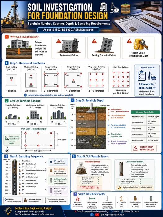
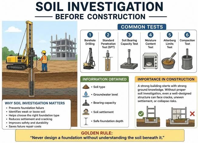
Boring depth must be sufficient to characterize all soil and rock materials that will influence the performance of the planned structure or earthwork. Minimum boring depths for each project type are determined by the applicable stress influence criterion, structure geometry, and client standard requirements.
Reference graphics
For spread footings, shallow foundations, and embankment centerlines, the minimum boring depth is the depth at which the stress increase from the applied load is less than or equal to 10% of the existing effective overburden stress. Using the 2:1 stress distribution approximation:
Where:
Minimum boring depth condition:
Where σ'_v₀ is the effective overburden stress at depth z (psf), computed as:
with γ' = effective unit weight (pcf), typically 55–65 pcf for saturated soils above the water table using buoyant correction, or 100–125 pcf total unit weight above the water table.
For a square footing with total applied stress q (psf) over area B²:
This simplification is used for preliminary depth estimates only; the full 2:1 calculation governs final depth determination.
| Project Type | Minimum Boring Depth (ft) | Governing Criterion |
|---|---|---|
| Embankment fill ≤ 10 ft high | 25 ft below existing ground | AREMA MRE Ch. 1 §1.4; USACE EM 1110-1-1804 §2-3 |
| Embankment fill > 10 ft high | 1.5 × embankment base width below existing ground; minimum 35 ft | 2:1 stress influence method |
| Track subgrade — existing mainline assessment | 15 ft below bottom of tie | FRA 49 CFR Part 213 Subpart C; AREMA MRE Ch. 1 |
| Bridge abutment — spread footing | 1.5 × footing width below footing base; minimum 20 ft below footing | AREMA MRE Ch. 8 §7; USACE criterion |
| Bridge abutment — pile supported | 20 ft below estimated pile tip depth | AREMA MRE Ch. 8 §7 |
| Bridge pier in waterway | 30 ft below streambed or 20 ft below estimated scour depth (greater) | FHWA HEC-18; AREMA MRE Ch. 8 |
| Retaining wall — spread footing | 2 × exposed wall height below footing base | AREMA MRE Ch. 8 §9 |
| Retaining wall — pile supported | 20 ft below estimated pile tip | AREMA MRE Ch. 8 §9 |
| Intermodal crane rail — spread footing | 30 ft below footing base | BNSF EI; AREMA MRE Ch. 8 |
| Intermodal crane rail — deep foundation | 20 ft below estimated pile tip | BNSF EI |
| Slope failure investigation | 15 ft below estimated failure plane; minimum 30 ft | AREMA MRE Ch. 1; USACE EM 1110-2-1902 |
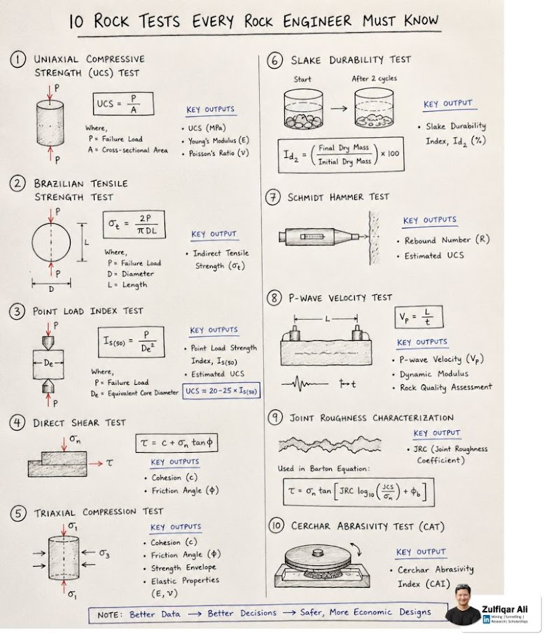
| Rock coring | 10 ft of competent core (RQD ≥ 50%, recovery ≥ 80%) | USACE EM 1110-1-1804 §5-7 |
CN’s bridge investigation requirements (Ruel, 2003) follow AREMA and add practical limits: borings extend below the depth significantly affected by the loads, river scour or deep shear — about twice the anticipated spread-footing width, or 10 ft below the estimated pile tip from a preliminary static analysis. One boring can be sufficient for a short bridge replacement in uniform, well-mapped geology; where practical, drill at the toe of the embankment rather than on the track. A railroad Bridges & Structures representative accompanies the crew.
CN also asks the geotechnical engineer for: allowable pile load vs. depth for each pile type (typical working load about 160 kips for a 14-in. H-pile), DRIVEN static capacity (compression and uplift), GRLWEAP driving criteria and maximum blows/in., p–y curves, and a linear lateral spring constant K per stratum for pile deflection up to about ½ in. at the bridge seat — so SPT, strength and unit-weight data must be sufficient for LPILE input in every stratum.
Table 5-S2. Guideline to extent of investigation (Look, 2007, Table 1.8, abridged)
| Development | Test spacing | Approximate depth |
|---|---|---|
| Bridges | Each pier | 4B–5B for shallow footings; 10 pile diameters in competent strata; in bedrock, ≥ 10 ft of coring and 3 pile diameters below founding level (RQD > 50%, moderately weathered or better) |
| Buildings | 65–165 ft | 2B–4B for pads/strips; 10 ft or 3 diameters below pile toe |
| Embankments | 80–165 ft at critical areas; 330–1,650 ft elsewhere | Beyond base of compressible alluvium at critical or suspect areas |
Source: Ruel, M. and KRK (2003). General Requirements for Geotechnical Investigations for Canadian National Bridge Construction Projects and “A Practical Approach to Lateral Loading on Piles for Railroad Bridge Design on CN Rail Projects.” CN Rail · Look, B. G. (2007). Handbook of Geotechnical Investigation and Design Tables. Taylor & Francis
Problem: A new 4,800-ft siding on a CSXT mainline corridor requires a 12-ft-high fill embankment with a finished base width of 80 ft (side slopes 2H:1V, 2 tracks, 14-ft track centers). Determine the minimum boring depth at the centerline boring location. The site is underlain by residual sandy clay with an estimated total unit weight of 118 pcf and the water table is estimated at 15 ft below grade.
Step 1 — Total applied stress at ground surface:
Embankment unit weight = 125 pcf (compacted granular fill assumed) Embankment height H = 12 ft Applied vertical stress at base = γ × H = 125 × 12 = 1,500 psf
Step 2 — 2:1 method — stress at depth z below base:
For the centerline boring, model the embankment as a strip load with effective width B = 80 ft, length L = 4,800 ft (long embankment; treat as infinite strip — use 2D approach):
Step 3 — Minimum depth condition:
Require Δσ_z ≤ 0.10 × σ'_v₀
Above water table: σ'_v₀ = 118 × z
Cross-multiply: 120,000 ≤ 11.8z (80 + z) = 944z + 11.8z²
Trial z = 40 ft: 11.8(40)(80 + 40) = 11.8 × 40 × 120 = 56,640 — too low Trial z = 60 ft: 11.8(60)(80 + 60) = 11.8 × 60 × 140 = 99,120 — close Trial z = 70 ft: 11.8(70)(80 + 70) = 11.8 × 70 × 150 = 123,900 ≥ 120,000 ✓
Result: Minimum boring depth ≈ 68 ft below existing ground at the centerline location.
CSXT Engineering Standard check: CSXT requires a minimum boring depth of 1.5 × embankment base width = 1.5 × 80 = 120 ft — this governs. Recommended boring depth = 120 ft.
This is a common finding in railroad geotechnical practice: the AREMA MRE or client standard minimum depth often exceeds the stress-influence calculation result. Always apply the more stringent criterion.
Problem: A bridge replacement project on a BNSF mainline requires exploration for a new pile-supported abutment. The existing abutment rests on 16-in.-diameter HP steel piles. Soil borings from the original construction (1962) indicate refusal at 45 ft. Determine the minimum boring depth for the new investigation.
Step 1 — Estimated pile tip depth:
1962 refusal depth = 45 ft below existing ground. Assume current pile tip ≈ 45 ft; anticipated new pile tip may be 40–55 ft based on load requirements.
Step 2 — Minimum boring depth per Table 5-1:
Pile-supported abutment: 20 ft below estimated pile tip depth
Boring depth = 55 ft (conservative pile tip estimate) + 20 ft = 75 ft minimum
Step 3 — BNSF EI check:
BNSF EI — Structures requires that all borings at pile-supported abutments extend a minimum of 20 ft into competent bearing material or to refusal, whichever is greater. Confirm with BNSF Division Engineer.
Recommended boring depth = 75 ft or 5 ft below first refusal horizon, whichever is deeper.
Problem: Prepare a preliminary boring scope for a new intermodal yard expansion for a Class I railroad client. The yard footprint is 2,200 ft × 800 ft (= 40.3 acres). The yard will include crane rail foundations (3 parallel cranes, each 2,100 ft long), truck pavement (20 acres), and a maintenance building (100 ft × 200 ft).
Boring count by zone:
Total preliminary boring count = 54 borings
Estimated depths:
Total footage = (33 × 65) + (10 × 20) + (5 × 60) + (6 × 15) = 2,145 + 200 + 300 + 90 = 2,735 linear ft
Laboratory testing must be assigned during planning — not after borings are complete. The testing matrix is organized by project feature, governing design calculation, and required test data.
| Feature | Design Calculation | Required Tests | Typical Quantity |
|---|---|---|---|
| Track subgrade — embankment | Settlement, bearing capacity | MC, Atterberg limits, USCS classification, consolidation | 1 consolidation per soft layer identified |
| Track subgrade — cut | Slope stability, shrink/swell | MC, Atterberg limits, unconfined compression (q_u), direct shear | 2–3 q_u per cut |
| Bridge abutment — spread footing | Bearing capacity, settlement | MC, Atterberg limits, consolidation, unconfined compression | Full suite per 5 ft depth change in critical strata |
| Bridge abutment — pile | Skin friction, end bearing | MC, Atterberg limits, triaxial UU (φ, c), grain size | Per critical layer |
| Intermodal pavement | Pavement subgrade design | MC, Atterberg, CBR (ASTM D 1883), M_r (AASHTO T 307) | 1 CBR per lift zone |
| Crane rail foundation | Settlement, bearing capacity | MC, Atterberg, consolidation, triaxial CU | Full suite per 10 ft in critical zone |
| Retaining wall | Earth pressure, stability | MC, Atterberg, direct shear (φ', c'), unit weight | 1 direct shear per soil unit |
| Slope stability | Shear strength | Triaxial CU + CD, direct shear (residual φ_r for existing landslides) | 3+ per failure surface soil unit |
| Ground improvement | Settlement after treatment | MC, Atterberg, consolidation, grain size for PVD drain design | Full suite per 5 ft in soft zone |
| Rock core (all structures) | Rock quality, bearing capacity | Point load (q_u conversion), core description (RQD), petrographic | 1 point load per 5 ft of core |
Reference graphics

Values from these correlations are estimates, not test results. State the equation ID and source when one is used, confirm the soil or rock is within its range, and calibrate against site testing before design.
BORING LOG — PROJECT: [Railroad] [Project Name] [Milepost]
Boring No.: B-1 Date Drilled: [Date] Sheet: 1 of 1
Location: STA 10+50 (MP 347.2 + 0.05 mi), 12 ft Right of CL, Looking Incr. MP
Ground Surface Elevation: 342.4 ft (NAVD 88) Drill Rig: CME-75 Track-Mounted
Drilling Method: Hollow Stem Auger (HSA) 3.25-in. ID Hammer: Auto SPT, 140 lb
Driller: [Name], Certified CSXT RWP Logger: [PE Name], PE
DEPTH SAMPLE BLOW DESCRIPTION
(ft) TYPE COUNT (USCS — ASTM D 2488/D 2487)
----------------------------------------------------------------------
0-2 - - Fill: silty CLAY, gray-brown, soft, moist
(CL per USCS, AASHTO A-6)
2-5 SPT-1 3/5/7 CLAY, gray-brown, soft to medium, wet
N₆₀ = 12 (corrected) MC = 38%
5-10 ST-1 - Shelby Tube (undisturbed sample for consolidation)
CLAY, gray, soft, wet; slight organic odor
MC = 44%, LL = 62, PI = 34 (CH)
10-15 SPT-3 2/4/4 CLAY, gray, soft; N₆₀ = 8; MC = 46%
15-20 SPT-4 4/5/6 CLAY, gray-tan, medium; N₆₀ = 11
20-25 SPT-5 6/8/10 CLAY, tan, medium-stiff; N₆₀ = 18
25-30 SPT-6 8/12/15 Transition to Sandy CLAY (SC); N₆₀ = 27
30-35 SPT-7 11/15/18 SAND, fine, silty, tan (SM); N₆₀ = 33
35-40 SPT-8 15/22/28 SAND, fine-medium, tan-gray (SP-SM); N₆₀ = 50
40 --- --- End of boring at 40 ft (No rock encountered)
Water Level: 6.2 ft below ground surface (measured 24 hr after drilling)
Casing: 3.25-in. HSA, pulled and abandoned
Reference graphics
Values from these correlations are estimates, not test results. State the equation ID and source when one is used, confirm the soil or rock is within its range, and calibrate against site testing before design.
| Sample | Depth (ft) | USCS Symbol | LL | PL | PI | MC (%) | γ_t (pcf) | q_u (tsf) | Notes |
|---|---|---|---|---|---|---|---|---|---|
| SPT-1 | 2–4 | CL | 48 | 22 | 26 | 38 | 113 | — | Jar sample |
| ST-1 | 5–7 | CH | 62 | 28 | 34 | 44 | 108 | 0.42 | Consolidation test specimen |
| SPT-3 | 10–12 | CH | 64 | 29 | 35 | 46 | 107 | — | Jar sample |
| SPT-5 | 20–22 | CL | 42 | 20 | 22 | 29 | 117 | 0.78 | q_u by UUC |
| SPT-7 | 30–32 | SM | NP | NP | NP | 14 | 124 | — | Grain size analysis |
| SPT-8 | 35–37 | SP-SM | NP | NP | NP | 12 | 127 | — | Grain size analysis |
LL = Liquid Limit; PL = Plastic Limit; PI = Plasticity Index; MC = Natural Moisture Content; γ_t = Total Unit Weight; q_u = Unconfined Compressive Strength (UUC); NP = Non-Plastic
Reference graphics
Reference graphics
Checklist · Part V · Subsurface Exploration
Use this checklist to verify planning completeness before submitting the Investigation Plan memorandum to the railroad client for approval.
Reference graphics
Levy (2010) recommends that owners prequalify contractors through a request for qualifications (RFQ) before bidding. His RFQ checklist asks for, among other things, years in business and any former company names, current backlog, three years of revenue, the largest recent projects, bonding capacity and insurance limits, projects not completed and why, any debarment, an attached quality control program, an attached safety program, and reportable accidents and OSHA violations for the past year. He recommends requesting the past five-year safety record and workers’ compensation experience modification rate (EMR), treating a rate below 1.0 as acceptable, and noting that a poor record takes about three years to work off. He also suggests calling past owners beyond the references listed, and asking them for other owners to contact.
For testing and inspection, Levy advises that certain inspections be contracted directly by the owner so the firm is impartial and works only for the owner. His list starts with inspecting soils before foundations are placed, inspecting compaction, and load testing piles. The testing RFQ should describe the project and schedule, list the services required, give an order-of-magnitude scope so firms can price it, and request hourly rates by staff level (regular and overtime) and unit prices for estimated test quantities.
At the preconstruction conference, the owner’s team should confirm the notice-to-proceed date, introduce the day-to-day staff, set communication channels and meeting protocol, verify insurance certificates for the contractor and each subcontractor, set procedures for questions and proposed change orders, and set the deadline for a baseline schedule and its update interval.
For railroad work: Add these points to the investigation planning checklist: confirm that the drilling subcontractor has railroad right-of-way experience, current contractor right-of-entry insurance, a safety program addressing roadway worker protection, and an acceptable EMR and OSHA history; confirm the testing laboratory’s accreditation and that acceptance testing during construction is contracted so that it reports to the railroad. Hold a short kickoff with the railroad’s representative to fix track access procedures, flagging requests, and the schedule for boring logs and lab data.
Source: Levy, S. M. (2010). Construction Process Planning and Management: An Owner’s Guide to Successful Projects. Burlington, MA: Butterworth-Heinemann (Elsevier), pp. 21–24, 28–29, 113–116. Summarized and paraphrased. Full reference under Supplemental Sources.
Cretu et al. treat risk identification as a short, facilitated, multidiscipline session. One to two hours is usually enough on an ordinary project. It is best run with a risk breakdown structure (RBS) as a checklist so that no category is skipped. Their construction RBS has seven top-level branches: design, environmental, real estate, economic, schedule, contracting and construction. Each branch breaks down into items such as design coordination, resource agency reviews, utility issues, impacts to existing operations and force majeure. The facilitator records every idea where the whole group can see it and holds back editing until later. The facilitator draws out risks with Socratic questions. One of the authors’ own examples is “Did we run into geotechnical problems at this location when the original foundations were installed?” A SWOT framing (internal strengths and weaknesses, external opportunities and threats) is offered as an alternative prompt.
The results go into a risk register with these fields: ID, RBS category, threat or opportunity, short title, description, trigger, probability (initially high >75%, medium ≈50%, low <25%), impact description, owner, response strategy and status. Each description should be specific, measurable, attributable, relevant and time-bound (SMART). The register is then vetted. Duplicates are merged, and many small related items, such as several minor geotechnical uncertainties, may be grouped into one risk for management. Black-swan events are noted, but they are not modeled. The authors’ list of workshop questions includes several on ground conditions: what geotechnical work has been done, what is assumed for cut/fill reuse and haul, what is assumed for stability of cuts and temporary support, and whether perched water or dewatering permits are involved.
For railroad work: Hold this session during investigation planning, before the boring layout is fixed. Add railroad-specific branches to the RBS: track access and work windows, flagging and protection, slow-order or traffic interruption exposure, signal and communication cable conflicts, and right-of-way or permit-to-enter limits. Then trace every high or medium geotechnical risk to a specific exploration, test or monitoring item in the scope, or record it as a risk the client accepts. The register then becomes the written basis for the scope and fee, and it carries forward into the report and the construction documents.
Source: Cretu, O., Stewart, R. and Berends, T. (2011). Risk Management for Design and Construction. Hoboken, NJ: John Wiley & Sons, pp. 237–244, 249–250. Summarized and paraphrased; figures reproduced for internal reference. Full reference under Supplemental Sources.
Use this checklist to verify planning completeness before submitting the Investigation Plan memorandum to the railroad client for approval.
Desktop Review:
Boring Layout:
Laboratory Testing:
Health and Safety / ROW Access:
Client Communication:
Reference graphics
Levy (2010) recommends that owners prequalify contractors through a request for qualifications (RFQ) before bidding. His RFQ checklist asks for, among other things, years in business and any former company names, current backlog, three years of revenue, the largest recent projects, bonding capacity and insurance limits, projects not completed and why, any debarment, an attached quality control program, an attached safety program, and reportable accidents and OSHA violations for the past year. He recommends requesting the past five-year safety record and workers’ compensation experience modification rate (EMR), treating a rate below 1.0 as acceptable, and noting that a poor record takes about three years to work off. He also suggests calling past owners beyond the references listed, and asking them for other owners to contact.
For testing and inspection, Levy advises that certain inspections be contracted directly by the owner so the firm is impartial and works only for the owner. His list starts with inspecting soils before foundations are placed, inspecting compaction, and load testing piles. The testing RFQ should describe the project and schedule, list the services required, give an order-of-magnitude scope so firms can price it, and request hourly rates by staff level (regular and overtime) and unit prices for estimated test quantities.
At the preconstruction conference, the owner’s team should confirm the notice-to-proceed date, introduce the day-to-day staff, set communication channels and meeting protocol, verify insurance certificates for the contractor and each subcontractor, set procedures for questions and proposed change orders, and set the deadline for a baseline schedule and its update interval.
For railroad work: Add these points to the investigation planning checklist: confirm that the drilling subcontractor has railroad right-of-way experience, current contractor right-of-entry insurance, a safety program addressing roadway worker protection, and an acceptable EMR and OSHA history; confirm the testing laboratory’s accreditation and that acceptance testing during construction is contracted so that it reports to the railroad. Hold a short kickoff with the railroad’s representative to fix track access procedures, flagging requests, and the schedule for boring logs and lab data.
Source: Levy, S. M. (2010). Construction Process Planning and Management: An Owner’s Guide to Successful Projects. Burlington, MA: Butterworth-Heinemann (Elsevier), pp. 21–24, 28–29, 113–116. Summarized and paraphrased. Full reference under Supplemental Sources.
Cretu et al. treat risk identification as a short, facilitated, multidiscipline session. One to two hours is usually enough on an ordinary project. It is best run with a risk breakdown structure (RBS) as a checklist so that no category is skipped. Their construction RBS has seven top-level branches: design, environmental, real estate, economic, schedule, contracting and construction. Each branch breaks down into items such as design coordination, resource agency reviews, utility issues, impacts to existing operations and force majeure. The facilitator records every idea where the whole group can see it and holds back editing until later. The facilitator draws out risks with Socratic questions. One of the authors’ own examples is “Did we run into geotechnical problems at this location when the original foundations were installed?” A SWOT framing (internal strengths and weaknesses, external opportunities and threats) is offered as an alternative prompt.
The results go into a risk register with these fields: ID, RBS category, threat or opportunity, short title, description, trigger, probability (initially high >75%, medium ≈50%, low <25%), impact description, owner, response strategy and status. Each description should be specific, measurable, attributable, relevant and time-bound (SMART). The register is then vetted. Duplicates are merged, and many small related items, such as several minor geotechnical uncertainties, may be grouped into one risk for management. Black-swan events are noted, but they are not modeled. The authors’ list of workshop questions includes several on ground conditions: what geotechnical work has been done, what is assumed for cut/fill reuse and haul, what is assumed for stability of cuts and temporary support, and whether perched water or dewatering permits are involved.
For railroad work: Hold this session during investigation planning, before the boring layout is fixed. Add railroad-specific branches to the RBS: track access and work windows, flagging and protection, slow-order or traffic interruption exposure, signal and communication cable conflicts, and right-of-way or permit-to-enter limits. Then trace every high or medium geotechnical risk to a specific exploration, test or monitoring item in the scope, or record it as a risk the client accepts. The register then becomes the written basis for the scope and fee, and it carries forward into the report and the construction documents.
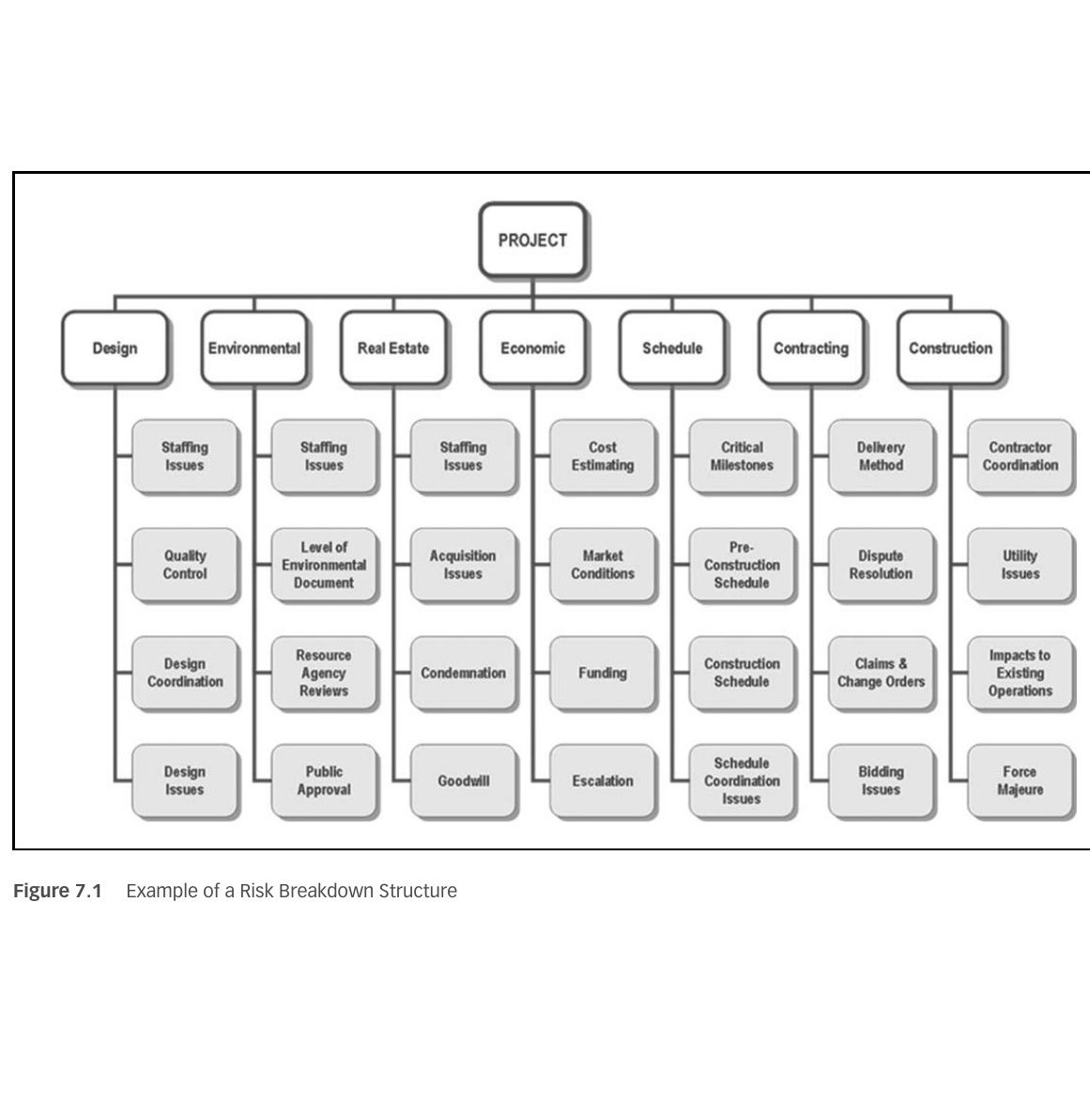
Source: Cretu, O., Stewart, R. and Berends, T. (2011). Risk Management for Design and Construction. Hoboken, NJ: John Wiley & Sons, pp. 237–244, 249–250. Summarized and paraphrased; figures reproduced for internal reference. Full reference under Supplemental Sources.
Reference graphics
Seeley explains how the civil engineering method of measurement (CESMM3, Class B) breaks a ground investigation into separately priced items, and why. Every group of test pits or borings generates at least two items: the number of holes and the aggregate depth. Costs that follow the number of holes (moving and setting up the rig at each location) are therefore kept apart from costs that follow footage. Further items cover depth in rock versus other material, hole support or backfill, samples by type and class, removal of obstructions (paid by the hour), and pumping (paid by the hour at a stated minimum extraction rate). Hand-dug pits are itemized separately because they cost more. The rate covers preparing and submitting records and results, but not their analysis, which is paid separately.
His sample bill (converted to US units) shows the pattern: 34 trial pits 10–16 ft deep with a minimum base area of about 24 ft², 446 ft of pit depth, 446 ft of backfill, 15 hours of obstruction removal and 30 hours of pumping at a minimum 35 gpm; 14 rotary core holes (4-in. minimum core), 367 ft of cored depth in holes 16–33 ft deep, 367 ft of grout backfill and 28 core boxes 10 ft long; 102 disturbed bag samples of at least 11 lb; and 56 thin-wall tube samples 4 in. × 24 in.
For railroad work: build the cost estimate and the scope of services the same way, so that a change in the number of borings or their depth reprices on its own rather than becoming a negotiation. Typical line items are: mobilization to the subdivision (fixed); moves between holes, priced per hole and split between hi-rail or on-track access and off-track access on the right-of-way; drilling footage in soil and rock in depth bands; coring footage; SPT and thin-wall tube samples counted separately; grouted abandonment per foot; standby hours for flagging delays or train traffic; and per-day items for flagging protection and roadway worker protection briefings where the railroad bills them. Keep laboratory testing and engineering analysis out of the field unit rates, as Class B does, so that adding borings at a growing slide does not quietly use up the analysis budget. A table set up like this also gives the client a clear, auditable invoice against the work authorization.
Source: Seeley, I. H. (1993). Civil Engineering Quantities, 5th ed. Basingstoke: The Macmillan Press, pp. 80–81. Summarized and paraphrased. Full reference under Supplemental Sources.
Q1. You are planning a geotechnical investigation for a new 6,500-ft siding for UPRR in southeastern Nebraska. The terrain is flat (slope < 1%) and the subsurface geology is Quaternary alluvial deposits — predominantly silty clay and fine sand. UPRR EIM §GT-100 requires a minimum of 1 boring per 1,500 ft on new sidings. The siding fill height is 6 ft with a base width of 60 ft. Determine (a) the number of borings required per UPRR EIM, (b) the minimum boring depth using the 2:1 stress influence method, and (c) whether the UPRR minimum or the stress-influence criterion governs.
A: (a) UPRR minimum = 6,500 ft ÷ 1,500 ft = 4.33 → minimum 5 borings (round up); add 1 boring at each end = 5 borings minimum. (b) 2:1 stress method: Q = γ_fill × H_fill = 125 × 6 = 750 psf. Strip load, B = 60 ft. Condition: 750 × 60 / (60 + z) ≤ 0.10 × 118 × z. Solve: 45,000 / (60 + z) = 11.8z → 45,000 = 11.8z(60 + z) = 708z + 11.8z². Trial z = 30 ft: 11.8 × 30 × 90 = 31,860 — too low. Trial z = 45 ft: 11.8 × 45 × 105 = 55,755 ≥ 45,000. Try z = 40 ft: 11.8 × 40 × 100 = 47,200 ≥ 45,000. → z_min ≈ 38 ft. (c) UPRR EIM §GT-100 for new siding embankment over alluvium requires minimum 25 ft below existing ground for fill ≤ 10 ft. The stress-influence result of 38 ft governs. Recommended boring depth = 40 ft (round to next 5-ft increment).
Q2. During the desktop review for a new NSR bridge replacement on the Piedmont Division, you find a 1967 boring log with SPT refusal at 22 ft. The 1967 log notes "weathered granite" at 18 ft. The new bridge will have drilled shaft foundations. What is your minimum rock boring depth for the new investigation, and what rock quality information must the boring provide per USACE EM 1110-1-1804 and AREMA MRE Chapter 8?
A: Minimum boring depth = estimated rock surface (22 ft) + minimum 20 ft of rock core into the zone being considered for shaft bearing = at least 42 ft total depth; 20 ft of NX or NQ core below the rock surface. Per USACE EM 1110-1-1804 §5-7, the rock core program must provide: (1) Rock Quality Designation (RQD) computed on ≥4.0-in. intact pieces per ASTM D 6032; (2) percent core recovery; (3) unconfined compressive strength (q_u) by point load index test or laboratory UCS; (4) description of weathering, fracture frequency, fracture fill character, and dominant fracture orientation. Per AREMA MRE Chapter 8, the drilled shaft bearing capacity computation requires q_u and a rock socket design that accounts for joint frequency, fracture condition, and weathering grade. We require at least 10 ft of core achieving RQD ≥ 50% and core recovery ≥ 80% before designating a horizon as competent bearing.
Q3. A CSXT emergency response task order requires you to mobilize to a slope failure by 6:00 AM. It is currently 10:00 PM. You have four personnel available, but only two hold current CSXT RWP certification. The other two hold expired CSXT RWP certificates (expired 4 months ago). Can the two with expired certificates enter the ROW if escorted by the two with current RWP? What is the correct course of action?
A: No — under CSXT's RWP program, personnel with expired certificates cannot enter the ROW under escort with a current RWP holder as a substitute for their own certification. CSXT's RWP program requires each individual who enters the ROW to hold a current, valid CSXT RWP certificate. Escorting covers visitors (e.g., owners, non-technical observers) with no independent ROW access requirement, not technical personnel who must enter the ROW to perform geotechnical work. Correct course of action: (1) The two personnel with current CSXT RWP mobilize immediately; they can begin the site assessment with a two-person crew. (2) Contact CSXT's RWP training coordinator at the emergency contact number to determine whether CSXT's emergency protocols provide any accelerated process for temporary ROW access for the expired-certificate personnel. (3) Plan to get the two expired personnel into the next available CSXT RWP class immediately — never allow a field team member's certification to expire during an active project. (4) Document in the project file that the limitation was identified and the emergency crew deployed with two certified personnel.
Q4. A G&W subsidiary project in Mississippi involves widening an existing embankment by 12 ft on each side (4-ft raise, resulting new base width = 88 ft). The existing embankment is 20 ft high. Your borings at the original embankment centerline reach 45 ft, but the G&W corporate engineering group asks whether you need borings outside the existing embankment toe (60 ft from CL). Explain your analysis using the 2:1 stress influence method to determine whether borings at the toe are necessary.
A: Yes — borings beyond the existing embankment toe are required. The critical stress zone extends laterally as well as vertically; the 2:1 stress distribution produces non-trivial stress increases at the proposed toe location. Existing centerline stress: γ × H = 125 × 20 = 2,500 psf. At the proposed new toe (60 ft from CL), the vertical stress from the widened embankment (B = 88 ft, half-width = 44 ft from CL) at 0 ft depth is already the overburden from the embankment fill, which the existing toe boring does not capture in terms of lateral extent. More critically, the slope stability analysis for the widened embankment requires shear strength data along the potential failure surface, which extends well beyond the current embankment toe — typically 0.5 to 1.0 × embankment height beyond the toe (10 to 20 ft). Borings should be placed at 20 to 30 ft beyond the proposed new toe (approximately 80 ft from CL) to characterize the natural foundation soils in the zone of the critical failure surface. Without these borings, the slope stability FS for the widened embankment is undocumented. Per AREMA MRE Chapter 1 §1.4, embankment stability must be verified before widening design is finalized.
Q5. You are preparing the investigation plan memorandum for an Amtrak NEC project in New Jersey. The NEC is operated as Class 7 (125 mph) at this location. The project involves replacing a signal bridge. Identify the five most important planning requirements that distinguish this investigation from a comparable investigation for a Class 4 freight railroad bridge project, referencing Amtrak Engineering Standards and applicable regulatory standards.
A: The five most important distinguishing requirements:
Values from these correlations are estimates, not test results. State the equation ID and source when one is used, confirm the soil or rock is within its range, and calibrate against site testing before design.
| Related Topic | Chapter |
|---|---|
| SPT corrections, sampling methods, boring log format | Chapter 6 |
| CPT, VST, PMT, and geophysical methods for site characterization | Chapter 7 |
| Soil and rock classification — USCS, AASHTO, AREMA MRE Ch. 1 categories | Chapter 8 |
| Groundwater characterization, piezometers, permeability testing | Chapter 9 |
| Bearing capacity calculations — Cooper E-80 loading, AREMA MRE Ch. 8 | Chapter 11 |
| Settlement analysis — consolidation, time rate, FRA and client geometry tolerances | Chapter 12 |
| Slope stability — AREMA MRE Ch. 1 embankment design; USACE EM 1110-2-1902 | Chapter 13 |
| Ground improvement — PVD spacing, preloading, schedule implications | Chapter 17 |
| Report preparation — investigation plan format per client requirements | Appendix E |
| Lab testing program — test standards, minimum quantities, acceptance criteria | Chapter 10 |
Table I-3: Emergency Response Contact Structure by Railroad Client (completed)
| Railroad | First Contact | Track Instruction Authority | Emergency Task Order Authority |
|---|---|---|---|
| CSXT | Division Roadmaster or Asst. Division Engineer | Division Engineer | Division Engineer — T&M against PSA |
| NSR | Roadmaster or Division Engineer | Division Engineer | Division Engineer — T&M against PSA |
| UPRR | System Operations Center (24/7) + Division Engineer | Division Superintendent | Region Engineer — T&M against PSA |
| BNSF | Division Superintendent or Roadmaster | Division Superintendent | Division Engineer — T&M against PSA |
| CPKC | Regional Operating Center + Division Engineer | Superintendent | Regional Engineering Manager — T&M |
| Amtrak | Amtrak Operations (24/7) + Chief Engineer on-call | Amtrak VP Engineering | Amtrak Capital Engineering — T&M |
| CN (US) | CN Operations Center + Division Engineer | VP Operations | Regional Engineering — T&M against PSA |
| CN (Canada) | CN Operations Centre + Regional Engineer | Superintendent of Operations | Regional Engineering — T&M against PSA |
| G&W Subsidiary | Railroad General Manager + G&W Corporate Engineering | G&W VP Operations | G&W VP Engineering — T&M |
We establish and document these contact chains at the beginning of every PSA engagement — not when the emergency occurs. The geotechnical firm's project manager and the on-call geotechnical engineer must have direct mobile phone numbers for every contact in the chain. We verify these contacts annually and update them when railroad personnel change roles.
The following timeline applies to all railroad emergency geotechnical response, regardless of client. Individual client protocols may require faster response on specific corridors or for specific event types.
Hour 0 — Notification Received:
Hour 0–4 — Mobilization and Site Arrival:
Hour 1–4 — First Professional Recommendation:
Day 1–5 — Emergency Investigation:
Month 1–6 — Permanent Repair:
We use the following framework when formulating emergency repair recommendations. Recommendations must be tailored to the specific conditions observed; this table provides starting points, not substitutes for engineering judgment.
| Failure Type | AREMA MRE Reference | Typical Emergency Repair Approach |
|---|---|---|
| Shallow slope failure (H < 10 ft) | MRE Ch. 1 §4.9 | Slope regrading to stable angle; rock buttress at toe; surface drainage improvement; erosion control blanket |
| Deep slope failure (H > 10 ft) | MRE Ch. 1 §4.9, MRE Ch. 8 §8 | Staged material removal; soldier pile wall; concrete block or gabion buttress; soil nail wall with geogrid facing |
| Embankment settlement or sinkhole | MRE Ch. 1 §4.5 | Compaction grouting; flowable fill void filling; temporary timber cribbing or bridging between ties |
| Bridge scour — abutment or pier | MRE Ch. 8 §7, FHWA HEC-23 | Emergency riprap placement; geotextile bag placement; temporary sheet pile or H-pile; flow diversion |
| Subgrade failure or mud boil | MRE Ch. 1 §4.5, CSXT/NSR/UPRR ES | Undercutting and replacement with granular fill; ballast injection; geotextile/geogrid installation under ballast |
| Retaining wall distress | MRE Ch. 8 §9 | Temporary rock buttress at wall base; sheet pile wall parallel to track; soil anchor installation |
Reference graphics
Hutchings summarizes research on scheduled overtime. In the first few weeks, total output per worker rises, though not in proportion to the added hours. After about 7 to 9 consecutive 50- or 60-hour weeks, weekly output falls to roughly what the same crew produces in a 40-hour week. After about eight more weeks, the losses cancel the early gains, so the whole overtime period produces no more work, and possibly less, than a normal schedule would have. Combined with premium pay, the productive value per wage dollar after several weeks drops below about 75% for five 10-hour days, below about 62% for six 10-hour days and below about 40% for seven 12-hour days. Productivity per hour recovers sharply when the crew returns to a 40-hour week. In his example claim on a public works job, lost labor productivity (about $2.4 million) was the largest single component of a total claim of about $7.4 million.
He distinguishes directed acceleration, where the owner orders the work sped up, from constructive acceleration. The latter requires an excusable delay, a request for an extension, refusal of the request, an order to finish on the original date anyway, and actual acceleration by the contractor. When a contractor is simply behind, he advises against an acceleration order. Instead, give written notice that the contract date will be enforced and ask for a revised schedule showing how the contractor will meet it. Means and methods, and responsibility for them, then stay with the contractor.
For railroad work: round-the-clock effort is appropriate in the first days of a slide or washout response, when restoring service drives every decision. Once the response becomes a permanent repair lasting weeks, plan for a sustainable pace: rotating crews, a defined second shift, or more equipment, rather than the same people working seven 12-hour days. Fatigue affects geotechnical observers as much as operators. Missed seepage, tension cracks or compaction problems late in a long shift carry a real cost. When the railroad sets a restoration date that cannot be met at normal production, record the instruction, any request for more time and the response, because those records determine later whether the extra cost was acceleration or part of the original scope.
Source: Hutchings, J. F. (2004). Project Scheduling Handbook. Civil and Environmental Engineering Series, Vol. 15. New York: Marcel Dekker, Inc., pp. 273–277. Summarized and paraphrased. Full reference under Supplemental Sources.
Technical quality is necessary but not sufficient for a successful railroad geotechnical practice. How we communicate — the speed, format, and clarity of our client communications — determines whether the railroad can actually use our work in their decision process. Different railroad clients have different communication cultures; we adapt to each.
When we encounter a significant finding in the field — an unexpected organic layer at a structure location, rock at a depth that contradicts a prior boring, artesian groundwater conditions, or a condition that materially changes the geotechnical risk picture — we communicate it to the railroad project manager the same day, not in the formal report.
CSXT communication culture: CSXT Division Engineers and Roadmasters expect directdirect, brief communications. A field finding email to a CSXT contact should be three to five sentences: what was found, at what depth and location, what it means for the project, and what we recommend doing next. CSXT engineering managers do not have time for long narratives; they need the bottom line first.
NSR communication culture: NSR Engineering Services operates a more formal review process than CSXT, with findings often routed through a designated project engineer in Roanoke. Field findings should be communicated first to the NSR project manager, who routes them to the appropriate NSR technical reviewer. NSR appreciates formal preliminary memoranda more than informal emails for significant findings.
UPRR communication culture: UPRR's system spans a vast geographic area with multiple regional engineering offices. Field findings must be communicated to the UPRR Region Engineer for the specific territory, not to a central corporate contact. Knowing which Region Engineer has jurisdiction over the project corridor is part of our project initiation checklist.
BNSF communication culture: BNSF's Engineering department operates through Division Engineers who manage capital programs within their divisions. Field findings are communicated to the BNSF Division Engineer and copied to the BNSF capital program manager. For significant findings on BNSF intermodal or major structural projects, a copy to BNSF Engineering management in Fort Worth is appropriate.
Amtrak communication culture: Amtrak's Engineering department is project-manager-driven. Field findings go to the Amtrak project manager first; the PM routes them to Amtrak's track, structures, or environmental engineers as appropriate. On NEC projects, findings that affect train operations must also be communicated to Amtrak's NEC operations management.
CPKC communication culture: CPKC is in a period of post-merger integration; communication channels are evolving. Confirm the appropriate project communication chain with CPKC Engineering at project initiation. Legacy CP projects: communicate to CP Regional Engineering manager. Legacy KCS projects: communicate to CPKC Division Engineer in the applicable US operating territory.
CN communication culture: CN's Engineering department is organized by region (Eastern, Western, US). Field findings go to the CN Regional Engineering manager for the project territory. For Canadian projects, CN's internal geotechnical engineering group in Winnipeg expects to be copied on significant geotechnical findings.
G&W communication culture: G&W subsidiary clients vary widely. The subsidiary's General Manager often needs to be included in field finding communications alongside the G&W corporate engineering group, because operational decisions — track restrictions, crew deployments, customer notifications — are made at the subsidiary general manager level.
At the end of each day of field investigation work, we send a brief daily summary to the railroad project manager. This is non-negotiable professional practice on all railroad geotechnical programs, regardless of whether the client has specifically requested it. The daily summary is a single paragraph or a short bulleted list containing:
The daily summary is not a formal document and does not carry a PE seal. It is a professional service communication that keeps the client informed and demonstrates that our investigation is progressing as planned.
We notify the railroad project manager by email when we reach 75% of the not-to-exceed (NTE) budget on any task order. The notification states: the current budget, the amount expended to date, the work remaining, our current estimate of total cost at completion, and our recommendation for how to proceed — either confirm that remaining work will be completed within the current NTE, or request authorization to increase the NTE.
We do not wait for the client to ask about budget status. We do not complete work beyond the NTE without prior written authorization. These are fundamental PSA disciplines that the railroad client's accounts payable and capital program management departments enforce regardless of how important the additional work is technically.
The CIOB Code defines change broadly: anything that affects the scope or brief, cost (including whole-life cost), time milestones, risk allocation, the working of the team, or any project process. It sets out a single route for every change:
Supporting tools:
The Code stresses that controlling change during design is far more effective than during construction, and that time is often more expensive than the material change itself.
For railroad work: On consulting assignments for a railroad, agree at the kick-off:
Keep a simple change register on the project. Log each scope change (a new boring offset because of a signal cable, a CPT replaced by a boring because of refusal, an added cross-section after a new tension crack) with its cost and schedule effect. Send the register with each progress report. The railroad then sees the cumulative effect before the invoice does.
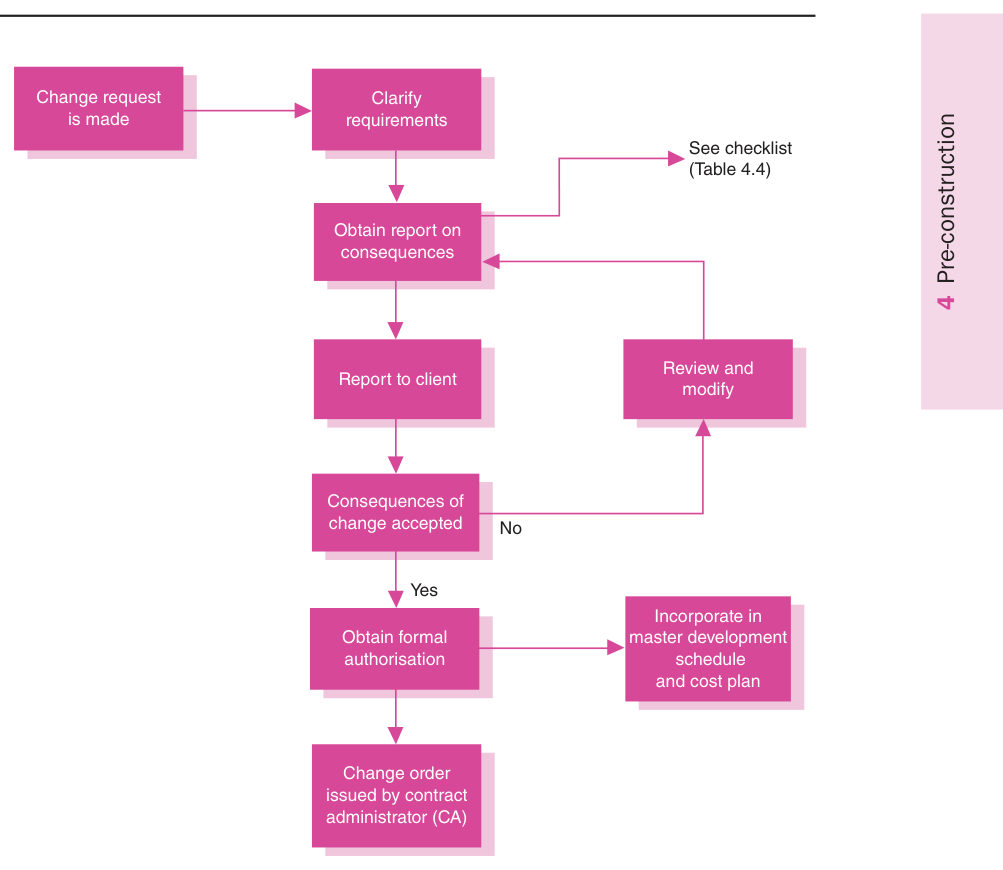
Source: Chartered Institute of Building (2014). Code of Practice for Project Management for Construction and Development, 5th ed. Chichester, UK: John Wiley & Sons, pp. 184–186, 236–238. Summarized and paraphrased; figures reproduced for internal reference. Full reference under Supplemental Sources.
| Railroad | Boring Log Format | Coordinate System | GIS Format | Database Delivery |
|---|---|---|---|---|
| CSXT | CSXT-specified gINT template | State Plane (NAD 83) | ESRI shapefile per CSXT GIS standard | CSXT Engineering Management System upload |
| NSR | NSR gINT template (obtain from NSR Engineering) | Virginia State Plane (FIPS 4501), NAD 83 | ESRI shapefile | NSR GIS database submission |
| UPRR | UPRR-specified format; confirm with UPRR Engineering | State Plane for project state, NAD 83 | ESRI shapefile | UPRR subsurface database upload |
| BNSF | BNSF Engineering preferred format; gINT acceptable | State Plane for project state, NAD 83 | ESRI shapefile | BNSF Engineering records |
| CPKC | CPKC format (confirm post-merger standard) | State Plane (US); NAD 83 (Canada) | ESRI shapefile | CPKC Engineering records |
| Amtrak | Amtrak Engineering preferred format | State Plane for corridor state, NAD 83 | ESRI shapefile per Amtrak GIS standard | Amtrak Engineering Management System |
| CN (US) | CN US Engineering format | State Plane for project state, NAD 83 | ESRI shapefile | CN Engineering database (CNES) |
| CN (Canada) | CN Canada Engineering format | UTM (NAD 83) or provincial grid | ESRI shapefile | CNES — Canadian operations |
| G&W | gINT or Log*Plot (confirm with G&W Corporate Engineering) | State Plane for project state, NAD 83 | ESRI shapefile | G&W Engineering records |
All boring logs must be delivered in both signed-and-sealed PDF and the native project file format (gINT project file, Log*Plot project file). Electronic data files allow the railroad's engineering team and future consultants to access and extend the boring database without re-entering data — a significant long-term value that distinguishes a professional deliverable from a mere PDF.
Physical sample and core retention requirements vary by client. The following represents minimum standards; client-specific requirements in the task order govern when they differ from these minimums:
| Railroad Client | SPT Jar Samples | Shelby Tubes (post-testing) | Rock Core | Disposal Notice Required |
|---|---|---|---|---|
| CSXT | 2 years post-report | Until lab QC sign-off | 5 years post-report | 60 days written notice to CSXT Engineering |
| NSR | 2 years post-report | Until lab QC sign-off | 5 years post-report | 60 days written notice to NSR Engineering |
| UPRR | Per UPRR EIM requirements; confirm at project initiation | Until lab QC sign-off | 5 years or as directed | Written notice to UPRR Engineering |
| BNSF | 2 years post-report | Until lab QC sign-off | 5 years post-report | Written notice to BNSF Engineering |
| CPKC | 2 years post-report | Until lab QC sign-off | 5 years post-report | Written notice to CPKC Engineering |
| Amtrak | Per Amtrak ES requirements | Until lab QC sign-off | 5 years post-report; NEC cores indefinitely | Written notice to Amtrak Engineering |
| CN | Per CN ES requirements | Until lab QC sign-off | 5 years post-report | Written notice to CN Regional Engineering |
| G&W | 2 years post-report minimum | Until lab QC sign-off | 5 years post-report | Written notice to G&W Corporate Engineering |
Core photography requirement: All rock core must be photographed in boxes before disposal, regardless of retention period. Core photographs, stored as high-resolution JPEG files with metadata tags identifying project, boring number, box number, and depth range, must be delivered to the railroad client at project closeout and retained in our project archive indefinitely.
Reference graphics
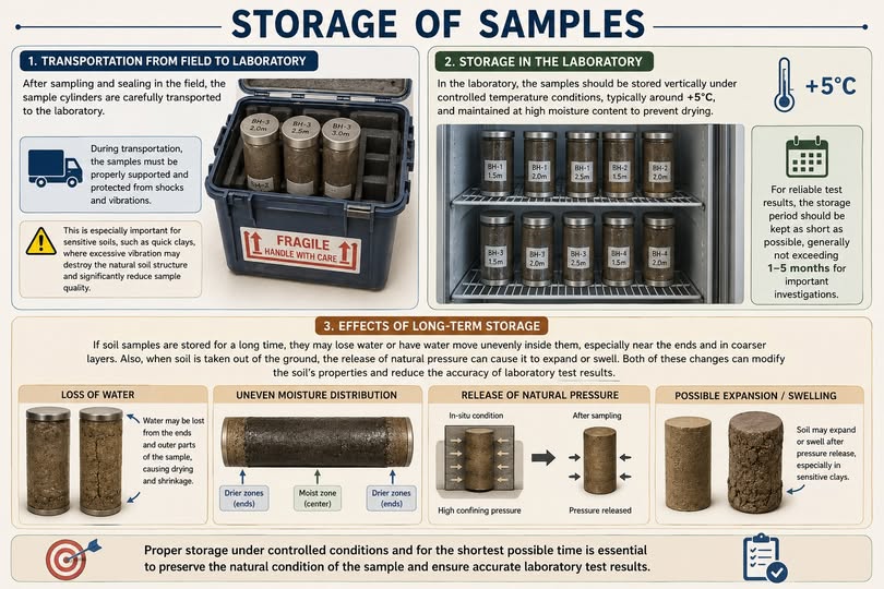
Every signed-and-sealed geotechnical deliverable for any railroad client is subject to independent peer review before issuance. The standard for "independent" is clear: the reviewer had no involvement in the investigation, analysis, or previous drafts of the document being reviewed.
| Deliverable | Minimum Reviewer Qualification | Review Level Required | Pre-issuance Client Review |
|---|---|---|---|
| Desktop Review Memorandum | Senior PE, same firm acceptable | Internal QC check | Not required |
| Assessment Report | Senior PE, same firm acceptable | Internal QC check | Not required |
| Reconnaissance Report | Senior PE, same firm acceptable | Internal QC check | Not required |
| Preliminary Geotechnical Report | Independent PE, 10 yr railroad GT experience | Full independent review | Recommended |
| 30% Geotechnical Design Memo | Independent PE, 10 yr railroad GT experience | Full independent review; signed seal required | Required — railroad Engineering Dept. |
| 60% Geotechnical Design Report | Independent PE, 10 yr railroad GT experience | Full independent review; signed seal required | Required — railroad Engineering Dept. |
| 100% Final Geotechnical Report | Independent PE, 10 yr railroad GT experience | Full independent review; signed seal required | Required — railroad Engineering approval |
| Emergency Phase 2 Letter Report | Senior PE, same firm acceptable | Review within 24 hours of issue | Notify only; no formal approval |
| Permanent Emergency Repair Report | Independent PE, 10 yr railroad GT experience | Full independent review | Required — railroad Engineering Dept. |
Client-specific peer review considerations:
Reference graphics
ASCE (2012) defines peer review as an independent assessment by experienced professionals who have not worked on the project or organization being reviewed. It distinguishes organizational reviews (how faithfully a firm or agency follows its own policies; usually confidential and often oral) from project reviews, which examine the technical results of a project at its current stage and are reported in writing. Peer reviewers are advisory; they identify gaps and do not direct changes, and the original engineer keeps full legal responsibility. A peer review is also not value engineering: VE asks whether the right overall solution has been chosen, while design peer review asks whether the chosen solution is engineered correctly.
The Manual lists circumstances that suggest a project review: a project larger or more complex than the team usually handles; new technology; difficulties on similar past projects; changed objectives or disputes; many offices or organizations; a fast-track schedule; limited budgets; staffing concerns or recent departure of key people; large potential liability or unusual public risk; uncertain status of work to date; and special environmental concerns. Typical scope items are design assumptions and criteria, applicable codes, spot-checks of calculations, clarity and completeness of reports, alternatives considered, judgment, constructability, proposed construction means and methods, and prospects of meeting objectives.
The process has six steps: request, scoping, reviewer selection, preliminary document review, on-site document review and confidential interviews, and reporting, followed by follow-up actions with measurable goals. Reviews held at earlier milestones usually yield more benefit than a review only at final design. A project review report typically covers scope and limits, schedule and status, phase reviewed, needed corrective actions, and issues for further evaluation. The EJCDC publishes a standard agreement for independent project peer review.
For railroad work: Several of the Manual’s triggers are common on railroad ground-hazard projects: emergency slide repairs designed on a compressed schedule, novel stabilization methods, high consequence of failure under traffic, and work spread across several offices. For such deliverables, set the peer review scope at the concept stage (failure mechanism, design parameters, analysis method) rather than only at final plans, and keep reviewer comments and their disposition in the project file.
Source: American Society of Civil Engineers (2012). Quality in the Constructed Project: A Guide for Owners, Designers, and Constructors, 3rd ed. ASCE Manuals and Reports on Engineering Practice No. 73. Reston, VA: ASCE, pp. 213–222. Summarized and paraphrased. Full reference under Supplemental Sources.
| Phase | Class I Freight (CSXT, NSR, UPRR, BNSF, CPKC, CN) | Amtrak | G&W Short Line / Regional |
|---|---|---|---|
| Desktop Review | Required — all projects | Required — all projects | Required — recommended even for small projects |
| Assessment | Required if no prior data | Required — all projects | Required — client often has minimal prior data |
| Reconnaissance | Required for new alignments and facilities | Required — all projects | May combine with design investigation |
| Study / Prelim. Eng. | Required for new facilities; alternatives analysis | Required — all projects | Grant-funded projects require study level |
| 30% Design | Required | Required — Amtrak ES governs | Required |
| 60% Design | Required | Required — Amtrak ES governs | Required |
| 100% Design | Required | Required — Amtrak ES governs | Required |
| Construction Services | Required on significant capital; recommended on all | Required — continuous inspection on NEC | Required on embankment and structure work |
The course presents the statement of work (SOW) as the document that defines scope, sets the customer’s expectations and can serve as the contract. A good SOW answers: what the purpose is and why the project is being done; who the immediate customer and the end user are; what the deliverables are and what support they need; and what the budget, final date, success measures, customer support and contingency plans are. Its generic contents are:
For railroad work: a culvert replacement investigation SOW might be built as follows (values illustrative):
Writing the client’s obligations into the SOW makes them visible when the schedule slips for reasons outside the consultant’s control.
Source: Skill Right (2013). Project Management Tools and Techniques: An Introductory Course in Project Management Foundations [training slides sponsored by Texas Instruments, Inc.; minor modifications by N. Santiago, Spring 2013 version], slides 26–35. Summarized and paraphrased. Full reference under Supplemental Sources.
Oberlender calls the work breakdown structure (WBS) the cornerstone of the work plan: to manage the whole project, you manage each of its parts. The WBS divides a project into levels (major facilities, sub-facilities, work items, tasks), and the lowest level is the work package, defined well enough to be measured, budgeted, scheduled and controlled. Code numbers link each package to the organizational breakdown structure (who does it), the cost breakdown structure (which account pays for it) and the CPM schedule (when it happens).
His procedure for building the plan:
The “not included / performed by others” lines on the work package are what prevent the same work from being done twice, or not at all.
For railroad work: A typical geotechnical scope breaks down cleanly. Level I covers desktop review, field exploration, laboratory testing, analysis, and reporting/GSPs. Level II splits field exploration into utility locates and railroad permits, flagging requests, drilling, in situ testing, and piezometer installation. Write a work package for each discipline lead and subconsultant (driller, lab, surveyor). Spell out in each package who requests and pays for flagging, who obtains right-of-entry, and who supplies track charts and as-built drawings. Hold the kick-off before the first track-time request, so that the two-week package return lines up with the railroad’s advance notice for work windows.
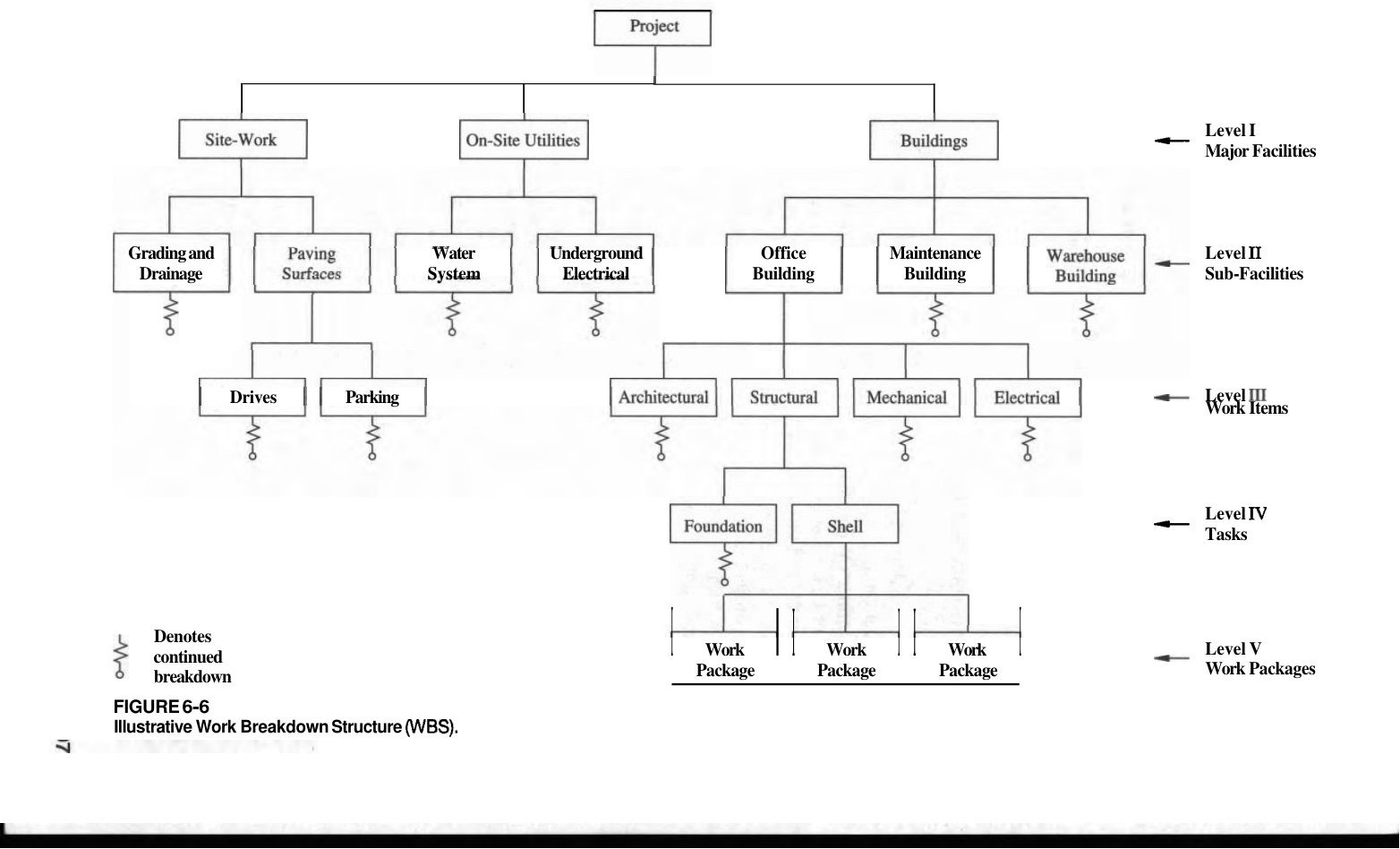
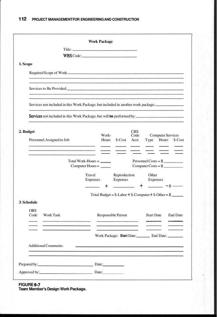
Source: Oberlender, G. D. (2000). Project Management for Engineering and Construction, 2nd ed. Boston: McGraw-Hill, pp. 99–115. Summarized and paraphrased; figures reproduced for internal reference. Full reference under Supplemental Sources.
From an international benchmarking study, Kelly, Male and Graham identify standard value opportunity points where a value study can be inserted in the project life cycle. These are a strategic briefing study (why invest, why now, for what purpose), a project briefing study (translating the business need into performance requirements), a concept design workshop, a detail design workshop and an operations workshop; a single charrette can take the place of some of the early studies. Each study has three phases. The orientation and diagnostic phase covers interviews, document review and a site tour. The workshop phase is typically half a day to a day within a four- to seven-day effort for a strategic study. The implementation phase, which the benchmarking found to be the most common point of failure, requires a named action plan. Their lever of value makes the timing point: effort spent at the strategy and objectives stages moves value far more than the same effort at the design or operations stage, and by final design the project’s value system is effectively locked. Two simple workshop tools support this. A time–cost–quality triangle has the team place one dot showing which of the three governs. A risk ranking from A to F combines high or low probability with consequence levels of “blocking force,” “turbulence” and “noise”; A–C risks go forward to analysis automatically.
For railroad work: Map these points onto the scope-of-services matrix. A short value and risk session at the concept or alternatives stage, before the boring program and the remedy type are fixed, is where the geotechnical engineer has the most leverage. It is the point to question whether the slide needs a wall or a drainage-and-buttress fix, or whether a culvert should be lined or replaced. Use the time–cost–quality dot to record whether track time or capital cost governs. On emergency slide work it is almost always time. On planned subgrade programs, cost and long-term performance often govern. Record the answer in the scope so that later choices about investigation depth and remedy are judged against the same priorities.
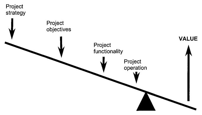
Source: Kelly, J., Male, S. and Graham, D. (2004). Value Management of Construction Projects. Oxford: Blackwell Science, pp. 102–109, 173, 299–302, 307. Summarized and paraphrased; figures reproduced for internal reference. Full reference under Supplemental Sources.
Rad treats an estimate as a forecast whose accuracy depends on how much is known about the project. Late in a project, with full information, estimates are seldom better than about ±3–4%. At inception, with little project-specific data, an order-of-magnitude estimate may end anywhere from about 30% to 330% of final cost. He cites professional-society guidance that the first formal published estimate should be within −40%/+100%. On that basis, a $100 estimate implies a final cost between $60 and $200.
The cheapest point to change a project comes early, while uncertainty is still high. Estimates refine progressively down the WBS: level 0 first, then level 1, and so on. Each refinement is an enhancement of the original estimate, not a new one, which makes variances easier to explain.
He separates three kinds of money that are often combined:
For early estimates he recommends range estimating. Each element gets optimistic, most-likely and pessimistic values, combined as (O + 4M + P)/6. In his example, values of 5, 8 and 35 give 12, not 8. This shows how a single-point “most likely” figure sits close to the optimistic end when the downside is long. When single-point estimates are rolled up they tend to understate cost, because estimators are optimistic.
For railroad work: The scope-of-services matrix should label each phase’s construction cost opinion with its expected accuracy, so that a desktop-stage figure for a slide repair is not taken as a budget. Carry contingency for geotechnical uncertainty, such as undercut depth, rock, groundwater and slide limits, separately from any railroad-held reserve for scope growth, for example added track miles or a changed alignment. Where data are sparse, give three-point ranges for the dominant quantities. As borings and lab results come in, reduce the contingency and record why it was reduced.
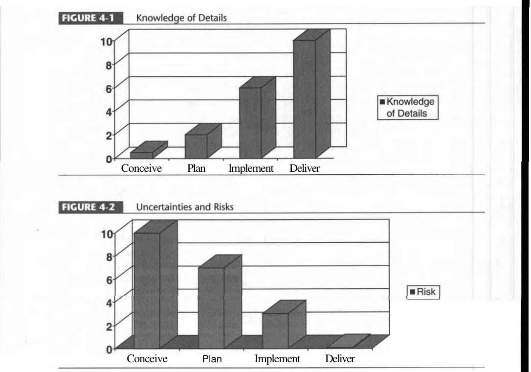
Source: Rad, P. F. (2002). Project Estimating and Cost Management. Vienna, VA: Management Concepts, pp. 43–49, 62–64, 111–112. Summarized and paraphrased; figures reproduced for internal reference. Full reference under Supplemental Sources.
Q1. You are providing geotechnical services to a BNSF Railway project manager for a new intermodal yard expansion in the Texas Gulf Coast region. Your investigation reveals a 12-ft-thick soft marine clay deposit at 15 to 27 ft depth. Your consolidation test results show C_c = 0.72 and c_v = 4.8 ft²/year. The BNSF project manager tells you that the crane rail foundations must be ready for concrete placement in 16 months. Which BNSF Engineering Instruction provisions govern your response, and what is your professional obligation to the project manager before the formal report is issued?
A: The applicable BNSF standard is the BNSF Engineering Instructions for Structures (BNSF EI Structures volume) for crane rail foundation design, supplemented by AREMA MRE Chapter 8 for foundation bearing capacity and settlement criteria. The governing performance criterion for crane rail differential settlement is contained in BNSF's intermodal facility design guidance, which specifies maximum differential rail settlement of ¼ in. per 50 ft — a tolerance far tighter than standard embankment subgrade requirements.
Our professional obligation to the BNSF project manager before the formal report is issued: Communicate the settlement timeline problem immediately — within 48 hours of receiving the consolidation test results. The calculation is straightforward: 90% primary consolidation of a 12-ft layer (single drainage assumed) with c_v = 4.8 ft²/year occurs at t₉₀ = 0.848 × H_dr² / c_v = 0.848 × 144 / 4.8 = 25.4 years without treatment. Even with PVD drains at 4-ft triangular spacing, achieving 90% consolidation in 16 months requires that surcharge loading must begin within weeks, not months, of our report issuance. We issue a preliminary technical memorandum — not a formal report — within 48 hours of receiving the consolidation data, clearly stating the schedule implication and recommending an immediate scope addition for a ground improvement feasibility study. We copy the BNSF Division Engineer and the BNSF Capital Engineering project manager.
Q2. A G&W subsidiary railroad in Louisiana is pursuing FRA CRISI grant funding for a 12,000-ft new siding on their network. The G&W corporate engineering group asks your firm to develop the geotechnical investigation scope. The subsidiary's General Manager suggests that G&W's prior inspection of the alignment is sufficient and no borings are needed. Explain your response, referencing applicable standards.
A: We respectfully decline to endorse a scope that eliminates borings for a 12,000-ft new siding on an FRA CRISI grant-funded project. Our response to the General Manager, coordinated through the G&W corporate engineering group, covers three points:
First, regulatory requirement: FRA CRISI grant funding requires that design be supported by site-specific subsurface investigation meeting applicable professional engineering standards. AREMA MRE Chapter 1 §1.4 requires that subgrade quality be determined before track design can establish blanket layer thickness and compaction specifications. A visual inspection does not produce the quantitative data required by AREMA MRE or by the FRA grant program's technical standards.
Second, professional liability: Signing a geotechnical report that supports a design without performing a defensible investigation creates direct professional liability for the engineer of record. If the siding subgrade fails after construction — due to soft soils, high water table, or organic deposits that a visual inspection would not detect — the geotechnical consultant and the G&W railroad share liability for the design deficiency.
Third, practical cost argument: The cost of a minimum reconnaissance investigation for a 12,000-ft siding — approximately $60,000 to $90,000 — is 0.5 to 0.75% of a typical siding construction cost of $12 million to $15 million. Discovery of soft soils requiring ground improvement during construction routinely costs $500,000 to $1,500,000 in change orders. The investigation is not an optional expense; it is risk management that the FRA grant program explicitly expects.
Q3. Your firm holds a PSA with NSR and is executing a task order for a bridge replacement investigation on the NSR Piedmont Division. The 60% GDR is 80% complete when NSR issues a revised edition of the NSR Engineering Standards Manual. The revision changes the minimum pile embedment depth requirement for the pile type you have already designed. What are your obligations, and what do you tell the client?
A: We notify the NSR project manager immediately — the same day we become aware of the revised NSR ESM edition — that a revision has been issued that affects our current design. We do not complete and issue the 60% GDR under the superseded standard without first confirming with NSR Engineering how to proceed.
Our specific obligations: (1) Obtain the current revised NSR ESM from NSR Engineering; confirm which edition and effective date applies to this project. (2) Review our pile embedment calculations against the new minimum depth requirement. If our calculations already meet or exceed the new minimum, document that compliance explicitly in the revised 60% GDR and reference the new ESM edition. (3) If our calculated pile embedment is less than the new minimum, we must revise our pile design recommendations before issuing the 60% GDR — we cannot issue a document that we know conflicts with the current version of the applicable standard. (4) If the revised minimum depth requires additional borings to confirm competent material at the new depth, we prepare a supplemental boring scope for NSR authorization before proceeding.
We tell the client: directly, transparently, and without delay. We do not quietly revise the document and hope the client does not notice which edition of the ESM we applied. Professional integrity and our PSA obligation require full transparency about standards changes that affect our work.
Q4. You are providing emergency geotechnical response to CSXT for a slope failure at milepost 347.2 on the CSXT Southern Division. After your site assessment, you determine that the failure is a shallow rotational failure with H = 8 ft, and the slope is currently stabilized with no active movement observed. Track geometry indicates a surface deviation of 1.8 in. over 31 ft at the slide location. The current CSXT track classification is Class 4 freight at 60 mph. What is your track restriction recommendation, and what is your technical basis?
A: Per FRA Track Safety Standards 49 CFR Part 213, the surface runoff limit for Class 4 track is 3 in. over 62 ft; a 1.8-in. deviation over 31 ft projects to approximately 3.6 in. over 62 ft if the deviation is uniform — which would exceed the Class 4 surface limit and technically require a speed restriction or correction. However, since the actual measured deviation is 1.8 in. over 31 ft and applies to a localized failure zone rather than a uniform settlement, we apply engineering judgment.
Our recommendation: Reduce operating speed to 25 mph (Class 2 restriction) over the affected 300-ft zone while emergency investigation and repair proceed. Technical basis: (1) The 1.8-in. surface deviation indicates the failure has affected the track structure, justifying an operational restriction. (2) The slope is currently stabilized with no active movement, justifying a slow order rather than a full closure. (3) Class 2 at 25 mph reduces dynamic wheel loads (DLF from ~1.4 to ~1.15), reducing the cyclic stress on the unstable subgrade by approximately 20%, reducing risk of renewed movement while the emergency investigation is underway. (4) We specify a CSXT Roadmaster re-inspection every 12 hours until emergency repairs are in place.
We communicate this recommendation verbally to the CSXT Division Engineer during the site visit and follow up with a written email to the CSXT Division Engineer and Roadmaster within 2 hours of leaving the site, citing the FRA 49 CFR Part 213 surface deviation criteria and our AREMA MRE Chapter 1 slope stability assessment as the technical basis.
Q5. Amtrak asks your firm to prepare a preliminary geotechnical report for a section of the NEC between Baltimore and Philadelphia where recurring track geometry deviations have been observed in the Amtrak track geometry car data for three consecutive measurement runs. The track is designated Class 7 (125 mph passenger operations). You find organic clay at 8 to 18 ft depth in your borings with natural moisture content w_n = 78% and liquid limit LL = 82%. What Amtrak Engineering Standards criteria govern your settlement analysis, and what preliminary finding must you communicate to Amtrak's project manager before the formal report is issued?
A: The governing Amtrak Engineering Standards criteria for this analysis are: Amtrak Engineering Standards — Track Subgrade and Earthwork for subgrade performance criteria; AREMA MRE Chapter 5 and 49 CFR Part 213 Subpart G for Class 7 track geometry tolerances (cross-level limit ½ in., surface runoff limit per Amtrak ES — typically more stringent than FRA minimum for NEC operations); and Amtrak ES Bridge and Structures standards for any settlement analysis at bridge approach locations within the affected zone.
The organic clay condition (w_n/LL = 78/82 = 0.95 — natural moisture nearly at the liquid limit) indicates a soil at or near the liquid state with essentially zero effective stress margin. This material is under active consolidation and is the almost certain cause of the recurring track geometry deviations in the Amtrak geometry car data.
Preliminary finding to communicate to the Amtrak project manager before the formal report: The preliminary finding is that the track geometry deviations are caused by ongoing primary consolidation settlement of a normally consolidated or lightly underconsolidated organic clay deposit at 8 to 18 ft depth. The settlement is ongoing — not a historical, completed event. Without intervention, the settlement will continue and the geometry deviations will worsen. For Class 7 NEC operations with a cross-level tolerance of ½ in., the expected differential settlement rate — even if only 0.1 to 0.2 in. per year — will require more frequent maintenance surfacing than is sustainable for high-speed passenger operations on the NEC. We communicate this finding in a preliminary technical memorandum within 48 hours of receiving the first laboratory test results, recommend that Amtrak Engineering evaluate whether the current maintenance cycle is sustainable while geotechnical remediation options are evaluated, and request authorization to expand our investigation scope to include ground improvement feasibility assessment.
| Topic | Chapter |
|---|---|
| Investigation planning — boring layout, depths, AREMA MRE Chapter 1 compliance | Chapter 5 |
| Drilling, sampling, SPT corrections, boring logs in client-required formats | Chapter 6 |
| In situ testing — CPT, VST, PMT, MASW for soft ground characterization | Chapter 7 |
| Soil and rock classification — USCS, AASHTO, AREMA MRE Chapter 1 subgrade categories | Chapter 8 |
| Groundwater — piezometers, permeability, seepage, dewatering for construction | Chapter 9 |
| Bearing capacity — Cooper E-80 loading, spread footings, piles, drilled shafts per AREMA MRE Ch. 8 | Chapter 11 |
| Settlement — consolidation time rate; comparison to FRA and client geometry tolerances | Chapter 12 |
| Slope stability — AREMA MRE Chapter 1 embankment design, USACE EM 1110-2-1902 | Chapter 13 |
| Seismic hazard and liquefaction — ASCE 7 site class; CPT and SPT methods | Chapter 14 |
| Pavement subgrade — CBR, resilient modulus, AASHTO 1993 design for yard paving | Chapter 18 |
| Ground improvement — preloading, PVDs, stone columns, DSM; client schedule implications | Chapter 17 |
| Retaining structures — earth pressure, wall types, drainage; AREMA MRE Chapter 8 | Chapter 16 |
| Railroad track subgrade — AREMA MRE Chapter 1 loading, subgrade failure modes, ballast design | Chapter 2 |
| Construction monitoring — compaction acceptance, pile driving, instrumentation | Chapter 15 |
| Report preparation — format by client (CSXT, NSR, UPRR, BNSF, CPKC, Amtrak, CN, G&W), GSPs | Appendix E |
| Laboratory testing program — test standards, testing plan, acceptance criteria | Chapter 10 |
Chapter 5 — Geotechnical Investigation Planning and Scope
Primary Source: USACE EM 1110-1-1804, Geotechnical Investigations, 1 January 2001; AREMA Manual for Railway Engineering (MRE), Chapter 1 — Roadway and Ballast; client-specific railroad engineering standards as cited.
Field case studies by Burt G. Look, from Earthworks: Theory to Practice – Design and Construction (CRC Press/Balkema, 2023), chosen for this chapter’s topics. Each is summarized from the book with its key figures and a closing note on railroad application added by the authors of this manual. Credit for the case material belongs to Look; see item S12 under Supplemental Sources.
Related section: 5.1 Background — Why Planning is a Billable Deliverable
In this 1988 case a developer sold apartments “off the plan” on one site founded on high-level weathered rock (shallow footings, 4,200 psf allowable bearing). When a second lot of similar size came up across the road, less than 66 ft away, the developer duplicated the project and skipped a site investigation, citing “experience” from next door.
The second site sat over a buried alluvial channel. A backhoe test pit to 10 ft, then borings to 20 ft and 49 ft, showed rock dropping to about 39 ft with compressible alluvium above. Shallow foundations were no longer viable and piles were required. The added cost cancelled the project about three weeks after start, and every purchaser’s deposit was returned.
For railroad work: the same assumption appears when a siding, second main or bridge replacement is designed from borings taken for the adjacent structure. Ground can change completely within a few track lengths, especially where a line crosses a filled valley or old stream course. The cost of the investigation is small next to the cost of finding this out during construction.
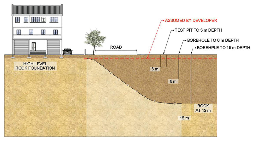
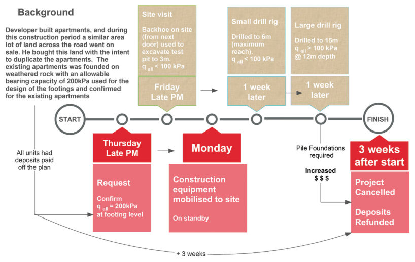
Source: Look, B. G. (2023). Earthworks: Theory to Practice – Design and Construction. CRC Press/Balkema. Case study §2.5, pp. 66–68. Summarized and paraphrased; figures reproduced for internal reference. Full reference under Supplemental Sources.
Related section: 5.2 Desktop Review — The Essential First Step
A deep basement was designed from a seepage model built on in-situ permeability tests, particle-size estimates and a sensitivity check of upper-95% flow rates. Access limits put every boring and CPT outside the building footprint, so the model was effectively two-dimensional. Extraction wells in the middle of the site then pumped far more water than predicted, while flows at the corners stayed manageable. Undersized pumps cost construction time, because a pump of the right capacity is seldom an off-the-shelf item.
Wall type, toe level and an underlying gravel layer were all examined and none explained the flows. Forensic data-gathering did: historical records showed a creek crossing the middle of the site 150 years earlier, infilled in the late nineteenth century and left undeveloped for another 50 years. That paleochannel, filled with loose sand, was the governing feature. Additional borings in detailed design had hinted at local loose sand, but the preliminary parameters were carried forward with only “minor” adjustments.
Look’s lesson is that each model (geological, geotechnical, analytical, design, construction) inherits the errors of the one before it, and the construction model is two steps removed from the analysis. The geological model has to envelop the others.
For railroad work: old valuation maps, historical aerials and early topographic sheets belong in the desktop review for the same reason. Filled creeks, ponds and borrow pits under an embankment or a new structure are the features a two-dimensional boring line along the track will not find.
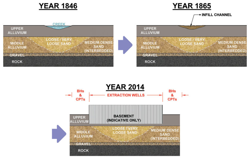
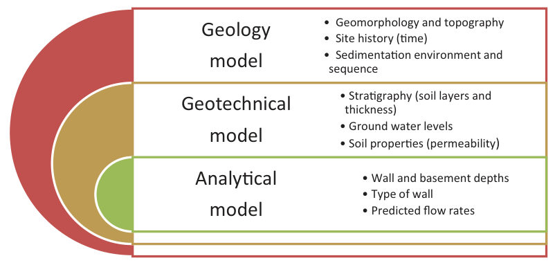
Source: Look, B. G. (2023). Earthworks: Theory to Practice – Design and Construction. CRC Press/Balkema. Case study §1.7, pp. 28–30. Summarized and paraphrased; figures reproduced for internal reference. Full reference under Supplemental Sources.
Authors: Daniel P. Colwell and Mario Ruel. This chapter was written and compiled by Daniel P. Colwell and Mario Ruel for Railway Ground Hazard Risk Management.
Technical content is drawn from the published sources below, and credit for that material belongs to their authors and publishers. Tables, equations and figures taken from a specific source are also cited where they appear.
File locations for these documents are listed under Supplemental Sources — LEVI Library.
Material in the green “Supplemental reference” boxes throughout this chapter was added from the following documents in the LEVI geotechnical library. Text is summarized or paraphrased; tables are reproduced with their original source noted; figures are reproduced from the cited document for internal reference use. Consult the original document before relying on a value for design. Blocks marked “After UFC 4-860-01FA (2004)” draw on item S10 and are rewritten for railroad clients. Blocks marked “After Selig & Waters (1994)” summarize item S11 for railroad clients; tables are condensed from the book and its figures are not reproduced. The Case Studies section summarizes case studies from item S12 by Burt G. Look; its figures are reproduced from the book for internal reference use, and the closing “For railroad work” note in each case study is added by the authors of this manual. Blocks tagged “Project management” summarize methods, examples and figures from the project-management, estimating and construction-management books listed here, applied to railroad work; the closing “For railroad work” note in each block is added by the authors of this manual.