
Geotechnical engineering libraryContact
Formerly Geo Rail Chapter 15 — Geotechnical Report Preparation
Geotechnical Services Manual for Railroad Clients
A Consultant's Reference for Delivering Geotechnical Engineering Services Across North American Railroad Capital Programs
Apps on dirtbert.com that support this chapter. Each one runs in a web browser on a desktop or a phone, with nothing to install. How to use the apps (I.3).
NANCY pages ask you to accept the Use and Disclaimers once in each browser.
The geotechnical report is the primary contract deliverable. It is the document upon which the railroad's project engineers, structural engineers, and construction contractors rely to design foundations, size retaining walls, specify embankment fill, and plan construction sequences. A technically sound investigation that is poorly reported is as damaging to a railroad capital program as a poorly executed one — and far more common.
This chapter defines the structure, format, content, and quality standards for geotechnical reports delivered to all nine client railroads. It distinguishes between a Geotechnical Data Report (GDR) and a Geotechnical Design Report (GDR/FGR), explains the executive summary writing framework, defines the required technical sections, specifies boring log and lab data presentation formats, describes calculation appendix organization, covers Geotechnical Special Provisions (GSP) integration, details PE seal requirements, and documents electronic deliverable formats, version control, and comment resolution protocols. All nine client engineering standards are cross-referenced.
All nine client railroads recognize — explicitly or implicitly — the distinction between two geotechnical deliverables:
The GDR presents factual subsurface data without interpretation or design recommendations. It is the appropriate deliverable for competitive bid projects where multiple engineering firms will use the same data to develop their own designs, and for early-phase investigations where design parameters have not yet been finalized.
GDR Contents:
GDR Users: Contractors preparing bids; design engineers developing conceptual foundations; railroad project development group.
The GDR/FGR (sometimes called a Final Geotechnical Report or Foundation/Geotechnical Report) presents factual data, interpreted parameters, analysis, and design recommendations. It is the primary deliverable for sole-source design contracts.
GDR/FGR Contents: Everything in the GDR plus:
FHWA adds a timing dimension to the GDR/FGR distinction. Issue a preliminary geotechnical report whenever early data or evaluation can shape the design — typically on large projects or complex sites where alignment or grade might change because of the geotechnical findings. The final report follows once alignment, grade and geometry are fixed and specific recommendations can be made. Whatever the format, FHWA lists five essentials: (1) all exploration data (profile, logs, lab and in-situ results, groundwater); (2) interpretation and analysis; (3) specific design recommendations; (4) discussion of anticipated problems and their solutions; and (5) recommended geotechnical special provisions. FHWA also notes that the report is used during design, during construction and after completion when resolving claims — one reason to write every statement as if it will be read by someone looking for a basis for a claim.
Source: Federal Highway Administration (2017). What is a Geotechnical Report? Geotechnical Engineering fact page
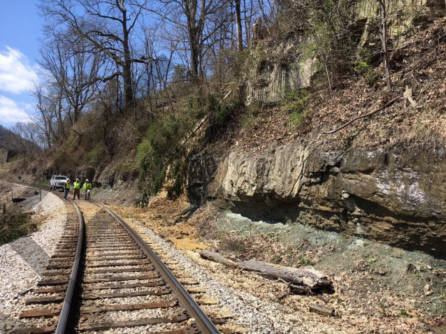
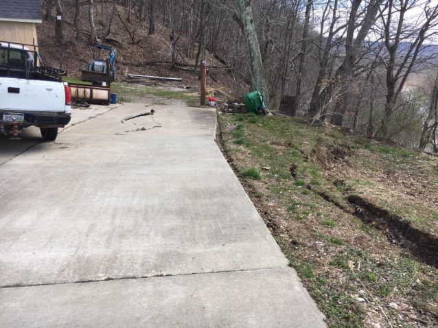
After a slope failure or washout the railroad needs a decision within a day or two, not a GDR. A 2018 preliminary site assessment for CSXT at MP BNA-56.0 (Shortline Subdivision, WV) illustrates the format. It is a two-page letter plus photographs and a sketch, issued the day after a site visit held two days after the event.
The structure — who/when/why, site and problem, observations, assessment, prioritized interim actions, and photos keyed to a sketch — is a useful template for GDR/FGR programs that begin with an emergency.
Source: Amec Foster Wheeler (2018). Preliminary Site Assessment of Slope Instability at CSXT MP BNA-56.0, Shortline Subdivision, near Clarksburg, WV (draft letter report, April 6, 2018)
| Railroad | Report Title Convention | Required Format | PE Seal Required | Electronic Format | Submittal Platform | Review Turnaround |
|---|---|---|---|---|---|---|
| CSXT | "Geotechnical Report — [Project Name]" | CSXT standard template | Yes (project state) | PDF + ProjectWise upload | ProjectWise | 20 business days |
| NSR | "Geotechnical Investigation Report — [Project ID]" | NSR standard outline | Yes (project state) | PDF email to PE of Record | Email + SharePoint | 15 business days |
| G&W | "Geotechnical Report — [Line Name, MP]" | Consultant format | Yes (project state) | PDF email | 15 business days | |
| UPRR | "Geotechnical Report — [Project Title, PSA No.]" | UPRR template preferred | Yes (project state) | PDF + UPRR portal upload | Procore/UPRR portal | 20 business days |
| BNSF | "Geotechnical Report — [Project Name, CWS No.]" | BNSF standard format | Yes (project state) | PDF + BIM 360 | BIM 360 (Autodesk) | 20 business days |
| CPKC | "Geotechnical Engineering Report — [Project No.]" | CPKC format (bilingual for Canadian projects) | Yes (project state/province) | PDF + CPKC SharePoint | SharePoint | 20 business days |
| Amtrak | "Geotechnical Report — [Contract No., Corridor]" | Amtrak PEIS format | Yes (project state) | PDF + Amtrak CMS | CMS portal | 30 business days (NEC) |
| CN | "Geotechnical Investigation Report — [CN Project No.]" | CN standard outline | Yes (project state/province) | PDF + CN SharePoint | SharePoint | 20 business days |
| AREMA | No specific format | Per AREMA MRE Ch. 1 Appendix | Per state board | Client-directed | Per contract |
The following section structure satisfies the requirements of all nine client railroads when tailored to the specific client format. Sections in bold are mandatory for GDR/FGR; unmarked sections are GDR-only.
Required elements:
The executive summary is the most-read section of any geotechnical report. Railroad project engineers often read only the executive summary before forwarding to procurement or construction. It must be self-contained and decision-ready.
Executive Summary Framework (PREP Method):
Length: 1–2 pages maximum. Never include equations, boring log references, or ASTM test numbers in the executive summary.
"This report presents the results of a geotechnical investigation performed at the NSR Shenandoah Valley Division bridge replacement at MP 128.4 near Waynesboro, Virginia. The investigation included four borings (B-1 through B-4) advanced to depths of 40–55 ft, Standard Penetration Tests at 2.5-ft intervals, and laboratory testing on selected samples. Subsurface conditions consist of 8–12 ft of mixed fill and residual silty clay overlying weathered greenstone bedrock, with competent rock encountered at 14–22 ft depth below existing ground surface..."
Reference graphics
Reference graphics
For GDR/FGR only. One subsection per analysis type performed:
E.3.8.1 Foundation Bearing Capacity (cross-reference Chapter 11)
E.3.8.2 Settlement Analysis (cross-reference Chapter 12)
E.3.8.3 Slope Stability (cross-reference Chapter 13)
E.3.8.4 Seismic Hazard and Liquefaction (cross-reference Chapter 14)
E.3.8.5 Pavement Subgrade / Track Subgrade (cross-reference Chapters 18, 2)
E.3.8.6 Ground Improvement (cross-reference Chapter 17)
Reference graphics
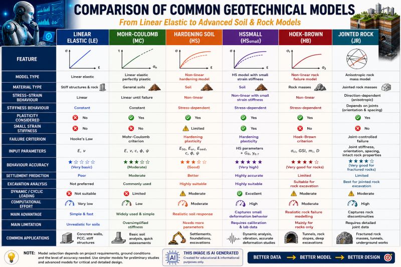
For track rehabilitation and substructure projects, the analyses section should present the following, so that the maintenance recommendation can be traced to evidence:
After Selig & Waters (1994), chs. 12, 14 and 16. Full reference under Supplemental Sources.
Numbered list of actionable engineering recommendations. Each recommendation must:
Reference graphics
"3. Design spread footings on the dense sand stratum (Stratum B) at a minimum depth of 4.5 ft below existing grade with an allowable bearing pressure of 3,500 psf (gross). Settlement under design load is estimated at 0.5–0.8 in. (see Section 8.2). Confirm footing bearing elevation in the field during excavation. Notify the geotechnical engineer if the sand stratum is not encountered within 1.0 ft of predicted depth."
Standard risk-allocation language required by all nine client railroads:
UPRR, BNSF, and CSXT require the limitations clause to include a specific sentence regarding the proprietary nature of client engineering standards referenced in the report.
Source: CSX Transportation (2020). Public Projects Manual, December 2020, incl. Soil and Water Management Policy
Profillidis summarizes investigation results in two deliverables: the geotechnical report and the geotechnical longitudinal section along the alignment. His example is the Channel Tunnel profile, routed within a blue chalk layer that proved resistant to water inflow (Figure E-11). The report should give clear recommendations on:
For linear railway projects, a longitudinal section that carries strata, groundwater, the track profile and the location of structures is often the most-used figure in the report. It belongs in the figures package with the boring location plan.
Figures · click to zoom
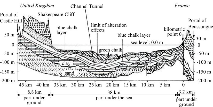
After Profillidis (2014), §9.2.5, Fig. 9.1. Full reference under Supplemental Sources.
Each boring log must contain (minimum fields per AREMA and client standards):
Header Block:
Column Layout (left to right):
| Column | Content |
|---|---|
| Depth (ft) | Depth scale, major depth marks every 5 ft |
| Graphic Log | USCS symbol pattern for each stratum |
| Recovery | Core recovery or SPT recovery (%) |
| SPT N-value | Raw N, N₆₀, (N₁)₆₀ (three columns) |
| Sample ID | Sample type (SS, ST, RC) and ID |
| Water Content (%) | Field moisture at sample depth |
| Description | USCS classification, color, consistency, structure |
| Remarks | Lab tests assigned, anomalies, notes |
Footer Block:
Reference graphics
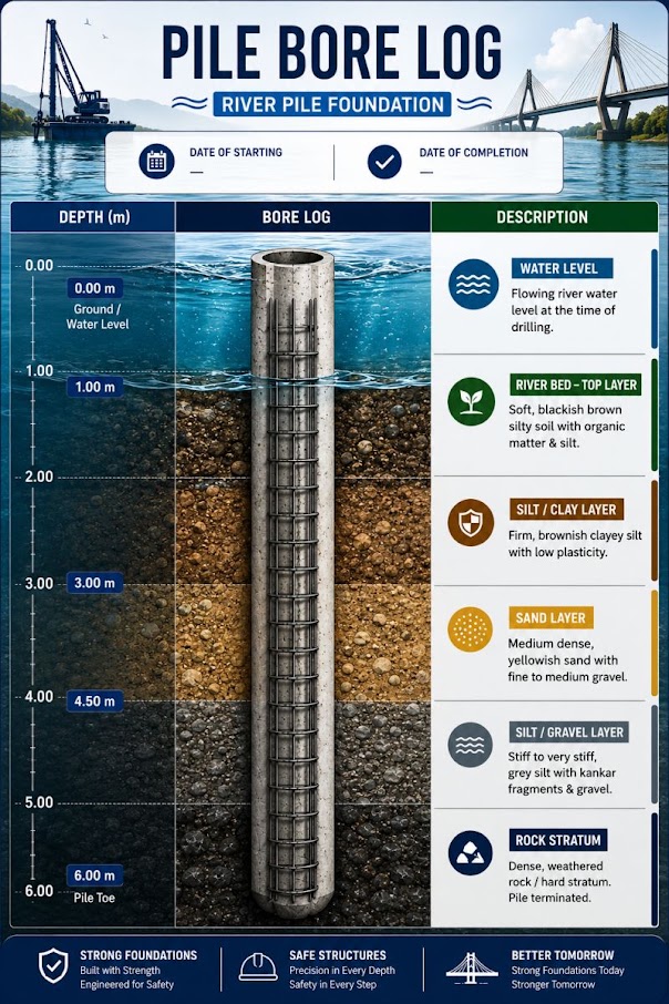
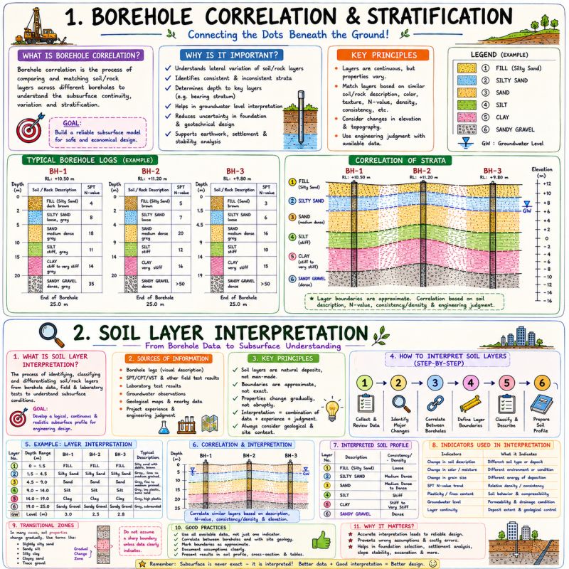
Use ASTM D2488 standard symbols for graphic log patterns. All nine client railroads accept ASTM D2488 symbols. Client-specific symbol modifications (e.g., CSXT uses a unique "ballast" symbol for borrow verification borings) must be noted in the legend.
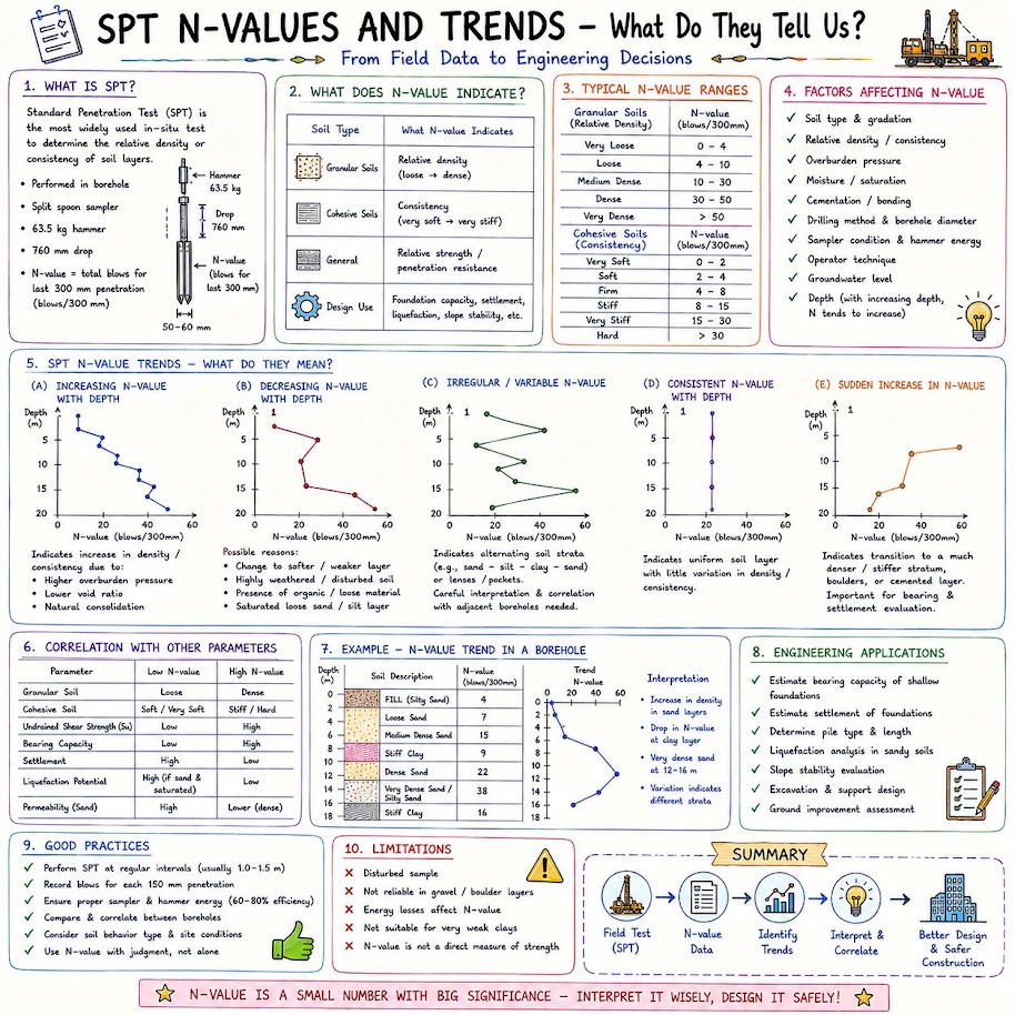
Plot N₆₀ as a bar chart on the boring log (bar length proportional to N₆₀; 50-blow refusal plotted as solid bar to the column edge with "50/X" notation). Tabulate raw N, E_m (%), C_B, C_R, C_S, N₆₀, C_N, and (N₁)₆₀ in the calculation appendix; show only N and N₆₀ on the boring log face for clarity.
Reference graphics
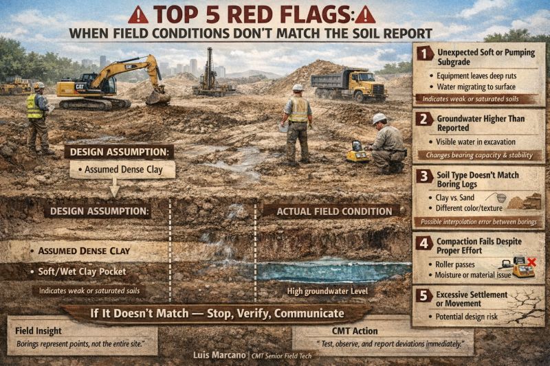
Levy (2007) notes that a large share of construction disputes arise during sitework, when excavation exposes ground that does not match what the geotechnical report led bidders to expect. A boring describes the strata only at its own location, and a hole drilled a few yards away can show something quite different. Standard report disclaimers say so, and often add that the owner should carry an allowance for foundation costs that cannot be known until construction. Levy points out that this cuts both ways: the disclaimer concedes that actual conditions will only be revealed by excavation, and the recommended allowance is really a contingency for the owner’s benefit, since the owner commissioned and paid for the report.
To support a differing-conditions claim the contractor must show that (1) the contract documents indicated certain conditions that formed the basis of the bid, (2) its reading of those documents was reasonable, (3) the conditions encountered differed materially, (4) they could not reasonably have been anticipated, and (5) the costs claimed arise solely from the difference. Recoverable delay costs can include direct labor and equipment, weather-shifted work, acceleration, idle rented equipment, extended field office and home-office overhead, and lost productivity. On unit-price public work Levy cites a common yardstick that quantities varying by 20% or more from bid quantities may justify repricing.
Source example. On a two-building campus project with an “unclassified” site, rock was found at about El. 162.8 where boring B-23 showed rock at El. 152, and other areas did not match the logs either. The owner rejected a $288,000 rock claim. By sliding a transparent overlay of the boring location plan over the building footprint, the contractor showed that the geotechnical engineer had plotted every boring about 50 ft west of its true position; shifted 50 ft east, all logs matched the field conditions, and the owner paid. On a second project, unsuitable soil below the footing “payline” was settled by agreeing on a reasonable limit to the depth the contractor “owned” on an unclassified site.
For railroad work: Boring location plans for embankment, culvert and bridge work should be tied to railroad stationing (milepost and track centerline offset) and surveyed coordinates, and checked against the plan sheets before issue; a plotting error is indefensible once a contractor finds it. Log presentation should state the date of water readings and note where conditions between borings are inferred. Keep disclaimer language factual and pair it with clear baseline statements (for example, expected top of rock or depth of soft fouled subgrade) so that the railroad and contractor share one reference for judging whether a condition is truly different.
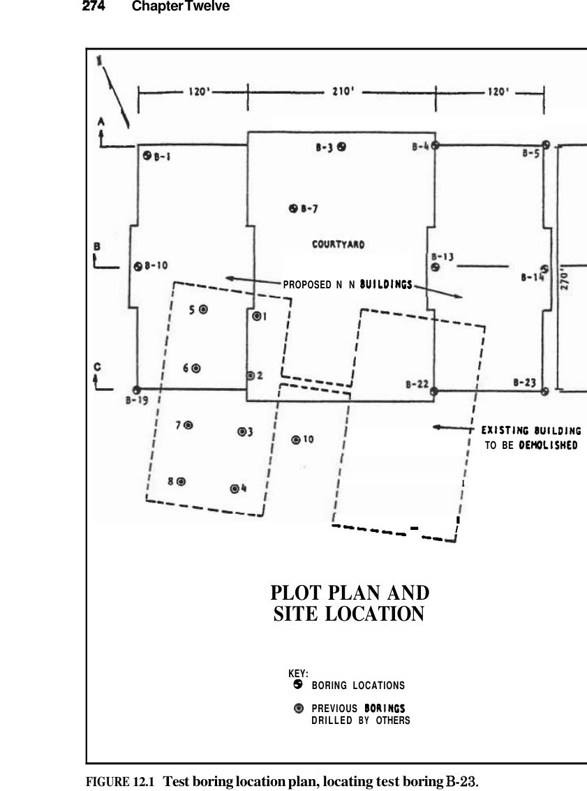
Source: Levy, S. M. (2007). Project Management in Construction, 5th ed. New York: McGraw-Hill, pp. 271–281. Summarized and paraphrased; figures reproduced for internal reference. Full reference under Supplemental Sources.
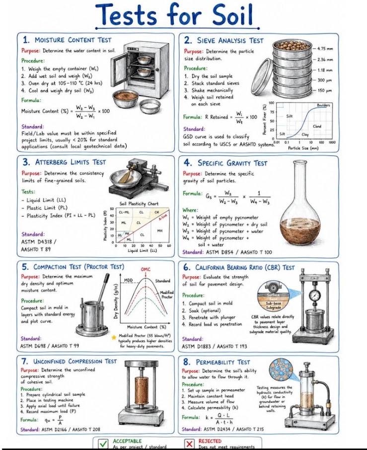
Present lab results in a single master table (Appendix B) with:
| Column | Description |
|---|---|
| Boring ID | Boring identifier |
| Sample ID | Sample number and type |
| Depth (ft) | Top and bottom of sample interval |
| USCS | Unified classification symbol |
| LL / PL / PI | Atterberg limits |
| % Fines | Percent passing No. 200 sieve |
| γ_d (pcf) | Dry unit weight from Proctor or shelby tube |
| w (%) | Natural water content |
| s_u (tsf) | Undrained shear strength (UU triaxial or vane) |
| c' (psf), φ' (°) | Effective strength parameters (CU/CD triaxial) |
| C_c / C_r | Compression indices (consolidation test) |
| c_v (ft²/day) | Coefficient of consolidation |
| σ'_p (tsf) | Preconsolidation pressure |
| k (ft/day) | Hydraulic conductivity |
| CBR (%) | California Bearing Ratio |
| Notes | Test method, remarks |
Completeness: Every sample assigned a lab test on the investigation plan (Chapter 5, Section 5.7) must appear in the table, even if the result is "not tested" due to sample disturbance, with a note explaining why.
Reference graphics
| Railroad | GDR Allowed? | FGR Always Required? | GSP Required in Report? | Calc Appendix Required? | Notes |
|---|---|---|---|---|---|
| CSXT | Yes (competitive bid) | Yes (sole source) | Yes | Yes | CSXT prohibits design recoms in GDR |
| NSR | Yes (competitive bid) | Yes (sole source) | Yes | Yes | NSR requires split submittal: data then design |
| G&W | Usually FGR only | Yes | No (separate GSP) | Yes | G&W accepts combined memo format for small projects |
| UPRR | Yes (competitive bid) | Yes (PSA) | Yes | Yes | UPRR requires all calc appx in MathCAD or Excel |
| BNSF | Yes (competitive bid) | Yes (PSA) | Yes | Yes | BNSF requires BIM 360 upload of all appx files |
| CPKC | Yes | Yes | Yes | Yes | Bilingual req't for Canadian territory reports |
| Amtrak | Yes (pre-PE) | Yes (PE phase) | Yes | Yes | NEC reports require independent peer review |
| CN | Yes | Yes | Yes | Yes | CN requires metric conversion table in appendix |
| AREMA | Per project | Per project | Recommended | Recommended | AREMA has no mandatory format |
Twort and Rees treat claims for unforeseen ground conditions as among the hardest a resident engineer handles. Their discussion is based on Clause 12 of the UK ICE conditions, which is broadly comparable to the differing-site-conditions clauses in North American contracts. The contractor may claim for physical conditions, other than weather, that could not reasonably have been foreseen by an experienced contractor. Their main points:
The authors note that a fair clause often means the owner pays no more than if the condition had been known and written into the contract.
For railroad work: The decision to issue a factual report only, or a factual report with a design report, determines what an “experienced contractor” can reasonably be expected to have foreseen. To make a later claim decidable:
When a claim arises, the boring logs, the report’s stated variability and the inspector’s daily records are the evidence the railroad will rely on.
Source: Twort, A. C., and Rees, J. G. (2004). Civil Engineering Project Management, 4th ed. Oxford: Elsevier Butterworth-Heinemann, pp. 212–219, 223–224. Summarized and paraphrased. Full reference under Supplemental Sources.
Goldbloom argues that subsurface risk belongs mostly with the owner, because only the owner has the time and budget to explore the site. Bidders get a few weeks to price the work and cannot drill their own borings. If each of several bidders had to do that, the owner would pay for the same exploration several times over. Borings and test pits show conditions only at the points sampled, so some differences during construction should be expected. A Differing Subsurface Conditions (changed conditions) article covers this. Its trigger is a condition that (1) differs materially from what the contract documents indicate, or (2) could not reasonably have been anticipated, and that (3) materially affects the cost of the work. The contractor must give notice before the condition is disturbed. The engineer then investigates, and if the claim is justified, an equitable adjustment is made in writing.
The book’s case history comes from a reservoir project that included a railroad relocation. Excavation for the dam was paid under two items, Earth Excavation and Rock Excavation. Rock was defined as ledge that needed drilling and blasting. At one abutment the contractor hit cemented glacial till that a 2½-CY shovel could not dig, and the borings had not shown it. The contract had neither a disclaimer nor a changed-conditions clause. The engineer still recommended paying for the extra drilling and blasting on force account, and the dispute was settled without litigation.
Goldbloom’s disclosure rules:
For railroad work: The GDR/FGR split described in this chapter maps onto Goldbloom’s factual/interpretive distinction. Bid packages for undercutting, cut-slope or culvert jobs should include the factual report: logs, lab data, groundwater observations with their dates, and GPR or ballast-fouling records. Interpretive design documents should be labeled as such. The pay-item definitions for excavation classes (common, rock, boulders, unsuitable subgrade) need to match how the logs describe materials, because the cemented-till case turned on that definition. Confirm with the railroad’s contracting group whether its standard agreement includes a changed-conditions article. If it does not, put the gap on the project risk register.
Source: Goldbloom, J. (1989). Engineering Construction Specifications: The Road to Better Quality, Lower Cost, Reduced Litigation. New York: Van Nostrand Reinhold, pp. 37–39, 182–186, 298–300. Summarized and paraphrased. Full reference under Supplemental Sources.
GSP are the contract-ready construction specification sections derived from the geotechnical design. They are included as an appendix to the GDR/FGR and are incorporated by reference into the project's construction contract. All nine client railroads require GSP for sole-source projects.
Each GSP section follows:
See Appendix C of this manual for complete GSP template language for: earthwork, fill compaction, ballast/subballast, ground improvement, deep foundations, dewatering, and instrumentation.
The geotechnical consultant produces GSP for geotechnical work only. Structural concrete, steel, and track work GSPs are the responsibility of the structural and track engineers. At the pre-design meeting, confirm the division of GSP responsibility in writing to avoid gaps or duplications.
GSPs should not contradict the owner’s own standard specification. The CSX Standard Specifications for Private Sidetracks contains these geotechnical requirements:
| Item | Requirement |
|---|---|
| Unsuitable material in cuts | Remove AASHTO A-2-6, A-2-7, A-4, A-5, A-6, A-7 to at least 2 ft below subgrade, ditch line to ditch line (more if local conditions require) |
| Muck in fill sections | Remove A-8 within the toes of slope; where fill exceeds 10 ft, excavate a width of 3× the fill height |
| Embankment lifts | ≤ 6 in. loose; no frozen or organic material; not on frozen ground; bench into existing slopes; no stones > 6 in. within 2 ft of subgrade |
| Embankment density | 95% of modified Proctor (ASTM D1557), with moisture adjusted |
| Finished subgrade | ± 0.10 ft of design; no depressions that hold water |
| Subballast | 95% modified Proctor; ± 0.10 ft; not placed on wet or rutted roadbed; AREMA Ch. 1 §2.11 materials; gradation (graded aggregate / crusher run) 1½ in. 100/100, No. 10 30–55 / 15–45, No. 200 5–12 / 5–12 |
| Geotextile (when specified) | On finished subgrade, no equipment on bare fabric, 2-ft end overlaps, 18-in. side overlaps, no longitudinal overlaps between ballast toes, turned down 2 ft at abutments |
| Around structures | No wet or impervious fill; 6-in. layers placed evenly on both sides; no large stones within 2 ft of arches, boxes or large pipes |
| Riprap | ¼ to 16 ft3 angular stone, minimum 3 ft thick on slopes in contact with streams |
Check against Section 15.2.1: the client compaction table there lists 90% relative compaction for CSXT embankments. The CSX sidetrack specification requires 95% of modified Proctor for embankments as well as subballast. Confirm the governing CSXT document for each project and cite it in the GSP.
Source: CSX Transportation (2016). Standard Specifications for Private Sidetracks (Industrial Sidetrack Manual), September 15, 2016
Haidar defines four kinds of float in arrow notation, where activity ij has duration dij and T(E) and T(L) are the earliest and latest event times:
Table E-PM1. Float definitions (after Haidar 2016, Eqs. 3.6–3.8)
| Float | Definition | Meaning |
|---|---|---|
| Total (TF) | T(L,j) − [T(E,i) + dij] | Delay that will not move completion; belongs to the path and is shared by every activity on it |
| Free (FF) | T(E,j) − [T(E,i) + dij] | Delay that will not move the early start of any successor; belongs to the activity |
| Interfering | TF − FF | Portion that, if used, takes float from successors |
| Independent | Successor early start − predecessor late finish − duration | Float available even in the worst case for both neighbors |
Because total float is shared, using it on one activity reduces it for all later activities on the path. Haidar stresses that the contract should say who owns float. The common default is that the project owns it and whoever uses it first gets it. An extension of time is then due only when an owner-caused event is predicted to push total float below zero on a path that is critical to completion. A contractor who wants a private buffer should show it as a time contingency in the baseline. NEC3 Clause 63.3 preserves terminal float when planned completion is earlier than the contract date. He also notes that in resource-constrained schedules the float concept, and sometimes the critical path itself, breaks down.
For railroad work: GSPs often create geotechnical hold points that act as schedule constraints. Examples include a settlement or piezometer monitoring period before the next fill lift or before final track surfacing, a load test before production piles, and a curing and verification period for treated ground. Write each hold point into the GSP with a stated minimum duration and the measurable criterion that ends it, so that bidders put it in the baseline schedule rather than treating it as float. Say whether an extension caused by monitoring results is an excusable delay, and coordinate that wording with the railroad’s contract staff. Treat track windows and outages as fixed constraints in the same way. A hold point that is clearly specified seldom produces a dispute; an unstated one usually does.
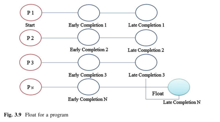
Source: Haidar, A. D. (2016). Construction Program Management – Decision Making and Optimization Techniques. Cham, Switzerland: Springer International Publishing, pp. 71–75, 78. Summarized and paraphrased; figures reproduced for internal reference. Full reference under Supplemental Sources.
The ASCE guide recommends a planned specification production process instead of copying the last similar job. Copied specifications carry irrelevant requirements and repeat past omissions. Small projects are not exempt: the guide notes that small jobs often produce large claims because of careless or incomplete documents.
Its flow chart has thirteen steps:
Steps 10 to 12 often repeat. Reviews should include field staff who will inspect the work and experienced construction people who can spot constructability problems.
The first document produced should be a scope-of-work memorandum. It lists the areas and types of work, the items furnished by the owner or others, and the specification sections and drawings required. The memorandum is a management tool and not a contract document. Its content later goes into the Summary of Work and the agreement, which lets technical sections stay generic.
Other points from the guide:
For railroad work: Treat GSP integration as a scheduled, budgeted deliverable, not a task for the end of the report. A geotechnical scope memo for a culvert replacement or slide repair would record:
Get the railroad’s standard specifications and agreement forms at Step 2, since many Class I railroads have their own. Include the resident engineer or construction manager in the constructability review.
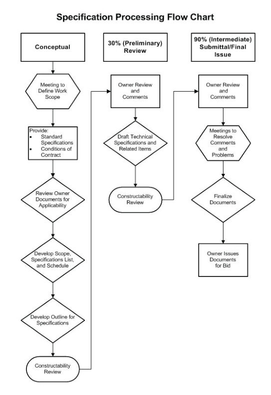
Source: ASCE Construction Institute Committee on Specifications (L. Eckersley, Chair) (2013). Preparation of Construction Specifications for Civil Projects. Reston, VA: American Society of Civil Engineers, pp. 6–12, 16–17, 22–23, 29–30. Summarized and paraphrased; figures reproduced for internal reference. Full reference under Supplemental Sources.
Spain’s commentary on how the CESMM3 measurement rules work gives several points that apply directly when a geotechnical report feeds a bid package.
Spain’s data chapter gives bulking factors for converting excavated volume to loose volume:
Table E-PM2. Table: Bulkage of excavation, percent increase over in-place volume (after Spain 1995, Chapter 9)
| Material | Bulkage (%) |
|---|---|
| Soil (general) | 25 |
| Gravel | 15 |
| Sand | 12.5 |
| Heavy clay | 30 |
| Rock | 30 |
| Chalk | 50 |
For railroad work: when the report’s recommendations become special provisions:
Source: Spain, B. (1995). Taking Off Quantities: Civil Engineering. London: E & FN Spon, pp. 10–11, 19, 23, 194. Summarized and paraphrased. Full reference under Supplemental Sources.
The calculation appendix must be organized to allow independent checking by the railroad's PE reviewer. Standard organization:
Reference graphics
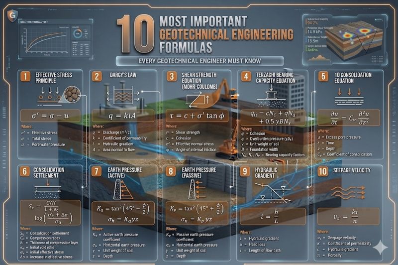
Each calculation subsection must show:
UPRR and BNSF: Require MathCAD Prime or Microsoft Excel (formula-visible) for all calculations. No PDF-only calculation packages.
Amtrak: Requires a separate independent design check by a second PE for all NEC foundation and retaining wall calculations.
| Railroad | Report Seal | Calc Appendix Seal | GSP Seal | Independent Check | Seal State |
|---|---|---|---|---|---|
| CSXT | Yes | Yes | Yes | No (standard projects) | Project state |
| NSR | Yes | Yes | Yes | No | Project state |
| G&W | Yes | Yes | No (for small projects) | No | Project state |
| UPRR | Yes | Yes | Yes | No (< $5M); Yes (≥ $5M) | Project state |
| BNSF | Yes | Yes | Yes | No (< $5M); Yes (≥ $5M) | Project state |
| CPKC | Yes | Yes | Yes | No | Project state/province |
| Amtrak | Yes | Yes | Yes | Yes (all NEC projects) | Project state |
| CN | Yes | Yes | Yes | No | Project state/province |
Digital PE Seal: All nine client railroads accept a digitally applied PE seal (per applicable state board rules) on PDF documents provided the seal meets state board digital signature standards. A scanned wet-seal image is not a digital seal — confirm with state board.
Multi-state projects: When a project crosses a state line (CSXT SE Division crossing Georgia/Tennessee, for example), the PE must be licensed in both states, or two PEs must co-seal (one per state). Confirm this with the client project engineer before the report is finalized.
Reference graphics
| Deliverable | CSXT | NSR | UPRR | BNSF | CPKC | Amtrak | CN | G&W |
|---|---|---|---|---|---|---|---|---|
| Main Report | PDF/A | PDF/A | PDF/A | PDF/A | PDF/A | PDF/A | PDF/A | |
| Boring Logs | ||||||||
| CAD Drawing (boring plan) | DWG 2018 | DWG 2018 | DWG 2020 | DWG 2020 | DWG 2020 | DWG 2020 | DWG 2018 | DWG/PDF |
| Calculations | PDF + source | PDF + Excel | PDF + MathCAD | PDF + Excel | PDF + source | PDF + source | PDF + source | |
| GSP | DOCX + PDF | DOCX + PDF | DOCX + PDF | DOCX + PDF | DOCX + PDF | DOCX + PDF | DOCX + PDF | |
| Lab Data | PDF + CSV | PDF + CSV | PDF + CSV | PDF + CSV | PDF + CSV | PDF + CSV | PDF + CSV | |
| GPR Data | Interpreted PDF | Interpreted PDF | Full dataset + PDF | Full dataset + PDF | Full dataset + PDF | Full dataset + PDF | Full dataset + PDF | PDF only |
Recommended file naming convention (compatible with all client document management systems):
[ClientCode]_[ProjectNo]_GeoRpt_[DocumentType]_Rev[##]_[YYYYMMDD].pdf
Example:
NSR_22-4182_GeoRpt_MainReport_Rev01_20260515.pdf
NSR_22-4182_GeoRpt_BoringLogs_Rev01_20260515.pdf
NSR_22-4182_GeoRpt_Calculations_Rev01_20260515.pdf
Revision tracking:
Include a revision history table on the cover page showing revision number, date, description of changes, and PE initials for each revision.
When the client returns review comments:
UPRR and BNSF require the Comment-Response Matrix to be submitted in their project management portal (Procore and BIM 360, respectively) with each revision.
Purpose and Scope: This Geotechnical Design Report presents the results of a subsurface investigation for the proposed CSXT Central Division track extension at MP 221.4 near Macon, Georgia. The investigation, performed in March 2026, included six borings (B-1 through B-6) advanced to depths of 20–40 ft, SPT testing at 2.5-ft intervals, Shelby tube sampling at three locations, and laboratory consolidation, triaxial, and Atterberg limit testing on selected samples.
Results: Subsurface conditions consist of 3–8 ft of loose to medium-dense silty fine sand fill (Stratum A) overlying soft to firm brown kaolin-rich clay (Stratum B, SPT N = 2–6 blows/ft, s_u = 320–480 psf) extending to 18–28 ft depth. Dense residual silty sand (Stratum C, N > 30 blows/ft) was encountered beneath Stratum B at all boring locations. Groundwater was encountered at 4–6 ft depth and stabilized at 3.5 ft below existing grade.
Engineering Conclusions: The soft Stratum B clay presents two critical design challenges: (1) total consolidation settlement of 8.4–11.2 in. under the proposed 12-ft embankment load, and (2) a factor of safety against slope failure of 0.82 under rapid fill placement — well below the CSXT-required minimum of 1.25. The dense Stratum C is adequate for spread footing or driven pile support of bridge structures within this project segment.
Practical Recommendations:
Below is the standard header format required by UPRR Engineering Instruction Manual for each calculation subsection:
━━━━━━━━━━━━━━━━━━━━━━━━━━━━━━━━━━━━━━━━━━━━━━━━━━━━━━━━━━━━
CALCULATION APPENDIX C-2: BEARING CAPACITY — PIER 2 FOOTING
━━━━━━━━━━━━━━━━━━━━━━━━━━━━━━━━━━━━━━━━━━━━━━━━━━━━━━━━━━━━
Project: UPRR Columbia River Bridge Replacement
Project No.: 2026-UPRR-0042
Client: Union Pacific Railroad
Location: Milepost 183.2, Portland Subdivision, OR
Date: June 1, 2026
Prepared by: [Name], PE, Oregon License No. XX-XXXX
Checked by: [Name], PE
DESIGN BASIS
Design load: Dead: 180 kips; Live: 220 kips (Cooper E-80, DLF 1.3)
Footing geometry: B = 8 ft, L = 10 ft, D_f = 4.5 ft (embedment)
Soil parameters: φ' = 34°, c' = 0 psf, γ = 121 pcf (from Table 5-2, Stratum C)
Water table: 7.5 ft below grade (SWL, boring B-3, 03/15/26)
References: Vesić (1975); AREMA MRE Ch. 8; UPRR Eng. Instr. Manual Sec. 4
CALCULATION
[Step-by-step calculation follows using all variables defined above]
RESULT
Allowable bearing capacity: q_allow = 4,200 psf (gross)
Applied pressure: q_applied = (180,000 + 220,000) / (8 × 10) = 5,000 psf — EXCEEDS
Action required: Increase footing to B = 10 ft, L = 12 ft → q_applied = 3,333 psf < 4,200 psf ✓
━━━━━━━━━━━━━━━━━━━━━━━━━━━━━━━━━━━━━━━━━━━━━━━━━━━━━━━━━━━━
Comment No. 07 (from NSR project engineer review, Report Rev01):
"Section 7.3: The settlement analysis uses C_c = 0.35 for Stratum B, but the lab data table (Appendix B) shows C_c values of 0.28, 0.31, 0.39, and 0.42 for the four consolidation tests. Please justify the value used or revise."
Response:
"Comment accepted. The design value C_c = 0.35 was selected as the average of the four laboratory consolidation test results (0.28 + 0.31 + 0.39 + 0.42)/4 = 0.35; however, this was not explained in the text. Per NSR Engineering Standards Manual Section 3 recommendation to use a conservative representative value for settlement calculations, we have revised to use C_c = 0.40 (the mean of the two higher values, reflecting the softer material likely to govern total settlement) and have updated Section 7.3 and Appendix C-3 accordingly. Settlement estimate is revised to 10.1–13.4 in. (was 8.4–11.2 in.). Recommendation 1 (staged construction with PVDs) is unchanged. See revised Section 7.3 and Appendix C-3, Rev02."
The following outline satisfies all nine client railroad requirements for a GDR/FGR:
COVER PAGE
TABLE OF CONTENTS
LIST OF FIGURES
LIST OF TABLES
1.0 EXECUTIVE SUMMARY
2.0 INTRODUCTION
2.1 Project Description
2.2 Scope of Investigation
2.3 Report Organization
3.0 SITE CONDITIONS
3.1 Location and Access
3.2 Topography and Drainage
3.3 Existing Structures and Track
3.4 Published Geologic References
4.0 FIELD INVESTIGATION
4.1 Boring Program
4.2 Drilling Methods
4.3 Sampling and Testing
4.4 Groundwater Observations
5.0 LABORATORY TESTING
5.1 Program Summary
5.2 Results Overview (detail in Appendix B)
6.0 SUBSURFACE CONDITIONS
6.1 Geologic Setting
6.2 Stratigraphy and Soil/Rock Description
6.3 Engineering Properties Summary Table
6.4 Groundwater Conditions
7.0 ENGINEERING ANALYSES
7.1 Foundation Bearing Capacity
7.2 Settlement Analysis
7.3 Slope Stability (if applicable)
7.4 Seismic Hazard and Liquefaction (if applicable)
7.5 Track Subgrade Evaluation (if applicable)
7.6 Ground Improvement (if applicable)
8.0 CONCLUSIONS AND RECOMMENDATIONS
9.0 LIMITATIONS AND CONDITIONS OF USE
FIGURES
Fig. 1 Site Location Map
Fig. 2 Boring Location Plan
Fig. 3 Geologic Profile (along alignment)
Fig. 4 Geologic Profile (cross-section)
Fig. 5 Instrumentation Plan (if applicable)
APPENDIX A BORING LOGS
APPENDIX B LABORATORY TEST DATA
APPENDIX C CALCULATIONS
APPENDIX D GEOTECHNICAL SPECIAL PROVISIONS
APPENDIX E FIELD EXPLORATION PHOTOGRAPHS
Oberlender’s chapter on design proposals is written for the design-side project manager, who must turn a sponsor’s request for proposal into an engineering scope, a work-hour budget and a schedule. The key steps:
He also recommends budgeting design in work-hours rather than dollars, because hours are what drive design.
For railroad work: The “mini-drawing” translates directly into a mini-report, a one-page-per-item dummy of the geotechnical report. List each figure (site location, boring location plan, subsurface profile along the track centerline, cross-sections at each repair station, stability output sheets), each appendix (boring logs, lab summary, calculations, GSPs) and each table, and assign estimated hours to every item. Building this dummy from the report outline in this appendix during the proposal makes the sheet and figure count visible. It also exposes scope the client may not have priced, such as a second cross-section for a slide that extends past the original limits, and gives a ready basis for the client-review allowance and the peer-review hours required under I.11.
Source: Oberlender, G. D. (2000). Project Management for Engineering and Construction, 2nd ed. Boston: McGraw-Hill, pp. 118–134. Summarized and paraphrased. Full reference under Supplemental Sources.
Reference graphics
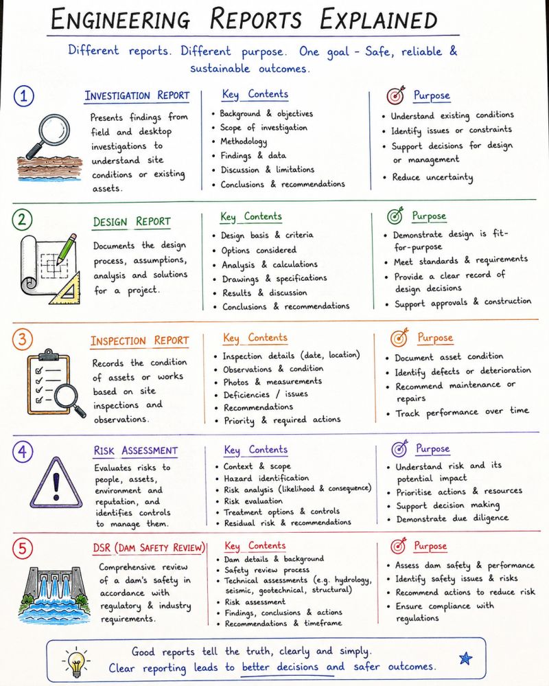
Forensic reports are read by lawyers as well as engineers. Rao (2016) recommends a fixed scope. Compulsory: survey and document the distress; review all design documents, the original investigation and the construction records; interview those involved. Optional: additional investigation, special tests and NDT of structural elements. The report should cover authority and scope, history, summary of original documents, data collected, interviews, meteorological and earthquake information, investigations and results, analysis and conclusions. Parameters must represent the actual site condition (avoid unvalidated empirical correlations), because the engineer must be able to justify them in court.
ISSMGE TC302 Task Force 10 reviewed about 100 failures from Asia, South America and Europe. Roughly half were caused by design shortcomings (including the ground model and parameters), about a fifth each by inadequate site investigation and unforeseen phenomena, and about a seventh by construction. In the Asian cases, inadequate investigation caused about half the failures, and in 60% of those no investigation had been done at all. Recommendations that belong in every railroad report’s QA process: a desk study with a geological framework on every project, adequate investigation funding, design by engineers who know their limits, independent checking or peer review of designs and construction methods, qualified oversight during construction, and publishing lessons from failures.
Source: Rao, V. V. S. (2016). “Guidelines for Forensic Investigation of Geotechnical Failures,” and Jessep, R. A., de Mello, L. G. and Rao, V. V. S. (2016). “Technical Shortcomings Causing Geotechnical Failures: Report of Task Force 10, TC 302.” In Rao and Sivakumar Babu (eds.), Forensic Geotechnical Engineering. Springer India
Hutchings describes changed conditions, also called unforeseen or differing site conditions, as a standard clause in federal contracts that is increasingly used by other public owners. The policy behind it is that the owner accepts certain subsurface and latent-condition risks so that bidders do not have to carry large contingencies for them. His examples of qualifying conditions include a buried pipeline that is missing from the drawings or shown in the wrong place, unusually severe weather for the season and location, and expansive clay in the excavation that was not identified in the geologic survey or the prior soil investigations. He notes that severe weather may be ruled excusable (time only) but not compensable.
He also lists constructive changes, informal owner acts or omissions that increase cost or time. These include defective plans and specifications, the engineer’s interpretation of documents, demanding a higher standard than specified, improper rejection of work, changes in method or sequence, and owner nondisclosure of pertinent facts. The contractor must give written notice within the contract period or may waive the claim.
To measure the time effect of a change after the fact, Hutchings uses three schedules:
The difference between the as-built and adjusted completion dates is the time attributable to that change. Before a change is made, a single revised as-planned schedule that includes the change shows its predicted effect on the end date.
For railroad work: the geotechnical report is the baseline against which a differing-condition claim is judged, so write it with that use in mind. Present factual data (logs, groundwater readings, lab results) separately from interpretation. State the limits of the data between borings. Include or reference all relevant information the railroad holds, such as historical borings, earlier slide reports and drainage records, because withholding pertinent facts can itself become a constructive change. During construction, document any suspected differing condition immediately: milepost, station and offset, depth, photographs, samples, and the work affected. Report it to the railroad’s project manager in writing the same day.
Source: Hutchings, J. F. (2004). Project Scheduling Handbook. Civil and Environmental Engineering Series, Vol. 15. New York: Marcel Dekker, Inc., pp. 209–212. Summarized and paraphrased. Full reference under Supplemental Sources.
Bissonette treats the line between a valid assumption and an unrecognized risk as central to planning. An assumption bounds the work to known constraints, or records a condition outside the team’s control that the stakeholders have agreed to. He applies a two-question “acid test” taken from the PMBOK® Guide:
If both answers are yes, the statement is a risk and must be moved to the risk register or reworded until it passes. A companion sentence form, “<assumption> may prove false, leading to <effect on objectives>,” makes the consequence explicit. His examples show the range of outcomes. One assumption is valid because a contract clause already provides an equitable adjustment if customer-furnished equipment arrives late. Another, “the team assumes no liability for scope omissions,” fails the test and should prompt more planning. He recommends an assumption register on every project, whatever its size. Its columns are number, description, “could it prove false?”, “if false, would it affect the project?” and “convert to a risk?”.
For railroad work: Geotechnical reports are full of assumptions: groundwater at the level measured during drilling, subsurface conditions between borings similar to those at the borings, no undocumented fill or buried timber trestle, drainage outfalls that remain functional, and tie and ballast renewal staying on the maintenance cycle. Run each one through the acid test before the report is sealed. Assumptions that pass belong in the limitations or design-basis section. Those that fail, such as a water level measured in a dry month at a site that seeps in spring, should be stated as a risk with a recommended response, for example a piezometer, a contingency quantity or a construction-phase observation. Including a short assumption register in the report appendix helps the railroad’s reviewers and the contractor see what the recommendations depend on. It also gives a clear basis for comparison if conditions found during construction differ.
Source: Bissonette, M. M. (2016). Project Risk Management: A Practical Implementation Approach. Newtown Square, PA: Project Management Institute, Ch. 5, “Assumptions Versus Risks” (unpaginated e-book; PDF pp. 62–65). Summarized and paraphrased. Full reference under Supplemental Sources.
Checklist · Part IX · Appendix
ASCE (2012) describes the design professional’s quality control as a plan that evolves with the project rather than a single check at the end. A typical project-specific design QC plan provides enough experienced staff; communication with the owner on priorities and within the design team; confirmation of field conditions, codes, standards and safety conditions that affect the design; preparation, review and coordination of drawings, estimates and specifications; scheduled reviews, audits and progress reporting; and specialty advisers on construction and maintenance who are not on the day-to-day team.
The QC focus changes by phase. In pre-design the parties agree on the QC plan. In schematic design the designer studies alternatives and the owner accepts a schematic design report. In design development alternatives and costs are refined, stakeholders such as regulators comment, and once the design development report is approved the design is “frozen.” In the contract documents phase QC includes detailed checking of computations, drawings and quantity take-offs, review of pay items and specifications, and constructability review. During bidding, the designer must correct ambiguities and errors that bidders identify before bids are due.
The Manual distinguishes the routine checking every design team does (dimensions, notes, cross-references, drawing–specification conflicts) from design reviews and audits. A design review is internal QC by team members and an experienced review board. A design audit is done by people outside the design team: an independent technical review if by others in the same firm, or an external peer review if by an unaffiliated organization. External peer review is recommended for complex, controversial, or high-risk projects. The Manual notes that owners and designers usually hold at least a final review at about 90% design completion.
For railroad work: Build the report checklist around these milestones: confirm the investigation scope against the project phase, check calculations independently (boring-depth, bearing, settlement, slope stability) before recommendations are written, reconcile the report’s quantities and pay items with the GSP and plan sheets, and hold a 90% review with the railroad’s engineering staff before sealing. Record who checked what and when, so the QC trail is part of the project file.
Source: American Society of Civil Engineers (2012). Quality in the Constructed Project: A Guide for Owners, Designers, and Constructors, 3rd ed. ASCE Manuals and Reports on Engineering Practice No. 73. Reston, VA: ASCE, pp. 193–196. Summarized and paraphrased. Full reference under Supplemental Sources.
Pre-Drafting
Report Drafting
Pre-Submittal
Post-Submittal
ASCE (2012) describes the design professional’s quality control as a plan that evolves with the project rather than a single check at the end. A typical project-specific design QC plan provides enough experienced staff; communication with the owner on priorities and within the design team; confirmation of field conditions, codes, standards and safety conditions that affect the design; preparation, review and coordination of drawings, estimates and specifications; scheduled reviews, audits and progress reporting; and specialty advisers on construction and maintenance who are not on the day-to-day team.
The QC focus changes by phase. In pre-design the parties agree on the QC plan. In schematic design the designer studies alternatives and the owner accepts a schematic design report. In design development alternatives and costs are refined, stakeholders such as regulators comment, and once the design development report is approved the design is “frozen.” In the contract documents phase QC includes detailed checking of computations, drawings and quantity take-offs, review of pay items and specifications, and constructability review. During bidding, the designer must correct ambiguities and errors that bidders identify before bids are due.
The Manual distinguishes the routine checking every design team does (dimensions, notes, cross-references, drawing–specification conflicts) from design reviews and audits. A design review is internal QC by team members and an experienced review board. A design audit is done by people outside the design team: an independent technical review if by others in the same firm, or an external peer review if by an unaffiliated organization. External peer review is recommended for complex, controversial, or high-risk projects. The Manual notes that owners and designers usually hold at least a final review at about 90% design completion.
For railroad work: Build the report checklist around these milestones: confirm the investigation scope against the project phase, check calculations independently (boring-depth, bearing, settlement, slope stability) before recommendations are written, reconcile the report’s quantities and pay items with the GSP and plan sheets, and hold a 90% review with the railroad’s engineering staff before sealing. Record who checked what and when, so the QC trail is part of the project file.
Source: American Society of Civil Engineers (2012). Quality in the Constructed Project: A Guide for Owners, Designers, and Constructors, 3rd ed. ASCE Manuals and Reports on Engineering Practice No. 73. Reston, VA: ASCE, pp. 193–196. Summarized and paraphrased. Full reference under Supplemental Sources.
| Topic | See Also |
|---|---|
| Investigation planning (boring scope) | Chapter 5 |
| Boring and sampling (log details) | Chapter 6 |
| In situ test results presentation | Chapter 7 |
| Soil and rock classification (USCS, RMR) | Chapter 8 |
| Groundwater data reporting | Chapter 9 |
| Bearing capacity calculations | Chapter 11 |
| Settlement calculations | Chapter 12 |
| Slope stability output | Chapter 13 |
| Seismic/liquefaction calculations | Chapter 14 |
| GSP template language | Appendix C |
| Borehole log template (blank form) | Appendix A |
| Lab test data table template | Appendix B |
| Final report delivery checklist | Appendix E |
Q1. An NSR project requires a GDR/FGR for a 60-ft bridge abutment replacement. The PE on the project is licensed in Virginia and North Carolina; the project is located in Tennessee. What action is required before the report can be sealed and submitted to NSR?
Answer: The PE must obtain a Tennessee Professional Engineering license (or Tennessee comity registration) before sealing a geotechnical report for a project located in Tennessee. Alternatively, a co-sealing arrangement with a Tennessee-licensed PE may be used if state board rules permit. NSR Engineering Standards require PE seal in the project state. This must be resolved before the report reaches its final review stage — not during the submittal process.
Q2. A consolidation test dataset from a BNSF project shows C_c values of 0.18, 0.22, 0.31, and 0.28 for four samples from the same stratum. (a) What is the mean C_c? (b) For design, should the mean or the upper-bound value be used? (c) How should the choice be justified in the report?
Answer:
Q3. A UPRR project is submitted as Report Rev01. The UPRR reviewer returns seven comments. Comment No. 3 states: "Increase FS_bearing from 2.5 to 3.0 for all spread footing designs." The consultant's PE believes FS = 2.5 is appropriate per AREMA Chapter 8 and the project-specific soil conditions. What is the correct response?
Answer: Do not silently ignore the comment or automatically comply without documenting the technical basis. The correct response is: (1) Write a Comment-Response Matrix entry for Comment No. 3; (2) Acknowledge UPRR's position; (3) Provide the technical rationale for FS = 2.5 (citing AREMA MRE Ch. 8, specific soil conditions, and available test data); (4) Propose a path to resolution — either the consultant revises to FS = 3.0 per client direction, or escalates to the UPRR chief engineer for a technical determination. The Comment-Response Matrix must record the disagreement, the consultant's justification, and the final resolution direction. "Not revised — see explanation" is a valid response category.
Q4. A CSXT geotechnical report for a bridge approach embankment must include GSP for staged construction. List the six required elements of a GSP section (per Section E.7.1) and give an example content item for each element.
Answer:
Q5. A BNSF geotechnical report is at Rev02 ("Issued for Client Review — 2nd Submittal"). The construction contract is awarded and the contractor begins mobilizing. The geotechnical engineer discovers that the consolidation test data from one boring was erroneously transposed (lab data was entered in the wrong row in the table), which changes the estimated settlement from 3.2 in. to 6.8 in. — above the FRA Class 4 tolerance. What must the consultant do?
Answer: Issue an immediate written notice (email + formal letter) to the BNSF project engineer and the project PE of Record, describing the error, the corrected analysis results, and the changed conclusion. Do not wait for the formal report revision cycle. Issue a Rev03 report correcting the error, with a clear revision history notation explaining the correction. The recommendations section must be updated — staged construction or ground improvement may now be required. Notify the structural engineer of record and the contractor if the change affects foundation design or construction sequence. This situation constitutes a changed condition that triggers the notification obligation in the Limitations clause. BNSF Engineering Instructions require all errata affecting design recommendations to be resubmitted within 5 business days of discovery.
Authors: Daniel P. Colwell and Mario Ruel. This chapter was written and compiled by Daniel P. Colwell and Mario Ruel for Railway Ground Hazard Risk Management.
Technical content is drawn from the published sources below, and credit for that material belongs to their authors and publishers. Tables, equations and figures taken from a specific source are also cited where they appear.
File locations for these documents are listed under Supplemental Sources — LEVI Library.
Material in the green “Supplemental reference” boxes throughout this chapter was added from the following documents in the LEVI geotechnical library. Text is summarized or paraphrased; tables are reproduced with their original source noted; figures are reproduced from the cited document for internal reference use. Consult the original document before relying on a value for design. Blocks marked “After Selig & Waters (1994)” summarize item S7 for railroad clients; tables are condensed from the book and its figures are not reproduced. Blocks tagged “Project management” summarize methods, examples and figures from the project-management, estimating and construction-management books listed here, applied to railroad work; the closing “For railroad work” note in each block is added by the authors of this manual.