
Geotechnical engineering libraryContact
Railway Ground Hazard Risk Management
Primary sources: AREMA Manual for Railway Engineering (MRE), Chapter 1 (Roadway and Ballast) and Chapter 8 (Concrete Structures and Foundations); FRA Track Safety Standards, 49 CFR Part 213; FRA Bridge Safety Standards, 49 CFR Part 237; Selig, E.T. and Waters, J.M. (1994), Track Geotechnology and Substructure Management; Li, D., Hyslip, J., Sussmann, T. and Chrismer, S. (2016), Railway Geotechnics; applicable ASTM standards as cited; and Chapters 2, 11–13 and 16–17 of this manual.
New chapter drafted September 2026 for the Railway Ground Hazard Risk Management reorganization. Verify client-specific values against the governing client standard before use on a project.
Apps on dirtbert.com that support this chapter. Each one runs in a web browser on a desktop or a phone, with nothing to install. How to use the apps (I.3).
NANCY pages ask you to accept the Use and Disclaimers once in each browser. MINA is a monitoring aid and is not for operational dispatch decisions.
Chapter 2 follows the load path from rail to the top of subgrade. This chapter picks up where that path ends: the foundation elements that sit below the subgrade surface, or that interrupt it, and on which long-term track performance ultimately depends. In a ground hazard program these elements are where most failures originate — an old end-dumped embankment that was never compacted, a soft clay foundation that keeps consolidating under heavier cars, a culvert that pipes backfill into its barrel, or a bridge approach where stiffness changes abruptly.
The chapter defines each foundation element, the function it performs for the track, the governing references (AREMA MRE Chapters 1 and 8, 49 CFR Parts 213 and 237, and client engineering standards), what typically goes wrong, and what an investigation must capture to evaluate it. It closes with a consolidated investigation matrix keyed to ASTM test methods, performance criteria, practical recommendations, a checklist, and practice questions.
The governing idea: the track is only as good as the least-capable element beneath it. Ballast and subballast can be renewed in a work window; embankment bodies, foundation soils and buried structures cannot. Identify and characterize them early, because they drive both the risk rating (Chapter 1) and the cost of any fix (Chapter 17).
For this manual, the track substructure is divided into the track bed (ballast, subballast and the prepared top of subgrade, covered in Chapter 2) and the foundation elements beneath and alongside it. The distinction matters because the two groups are maintained, inspected and funded differently.
| Foundation Element | Function for the Track | Governing References | Typical Geotechnical Concern |
|---|---|---|---|
| Embankment (fill) body | Raises the formation to grade; carries track load to the foundation | AREMA MRE Ch. 1 (Roadbed); client earthwork specs | Uncompacted historic fill, ballast pockets, side-slope instability |
| Cut section and cut slopes | Lowers formation to grade through high ground | AREMA MRE Ch. 1 (Roadbed) | Seepage, softening of cut floor, slope raveling, rockfall |
| Foundation soils beneath fills | Supports the embankment and train load | AREMA MRE Ch. 1; Chapters 11–13 | Soft clay, organics, sensitive or collapsible soils, karst |
| Drainage elements (ditches, underdrains, culverts) | Keep water out of and away from the substructure | AREMA MRE Ch. 1 (Culverts); 49 CFR 213.33 | Blockage, piping along barrels, corrosion, overtopping |
| Bridge approaches and transition zones | Transition between ballasted track and a rigid structure | AREMA MRE Ch. 1 and Ch. 8; 49 CFR Part 237 | Differential settlement ("bump"), stiffness change, backfill loss |
| Structural foundations adjacent to track | Support bridges, walls, retainers, signal and catenary structures | AREMA MRE Ch. 8; client standards | Surcharge from train load, scour, settlement, lateral movement |
| Crossings, turnouts and special trackwork | Carry concentrated and impact loads | AREMA MRE Ch. 1 and Ch. 5; client standards | Poor drainage, pumping, rapid geometry loss |
| Utility and pipeline crossings | Third-party facilities within the substructure | AREMA MRE Ch. 1 (Pipelines); client utility-crossing rules | Settlement or voids from leaks, trench backfill, casing failure |
The consultant's responsibility is to identify which of these elements are present at a site, which one governs performance, and whether its condition is changing. A site that "just needs surfacing" every year is rarely a ballast problem — it is usually one of the elements in this table.
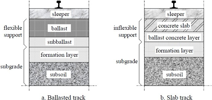
Ballasted track is a flexible support; slab track (concrete slab or asphalt over a ballast-concrete layer and an anti-frost layer) is an inflexible support. Ballasted track remains the norm because it tolerates differential settlement, costs much less to build and gives good lateral resistance even at high speed. Slab track is most effective in tunnels, where it allows a smaller cross-section and reduces maintenance, but it is noisier.
The choice turns on construction cost (much higher for slab), maintenance cost (much higher for ballast) and the technical needs of the site. German figures from 2008 put slab track at €575–680 per meter against €365 per meter for ballasted track, before the extra earthwork and subgrade work that slab track needs. Slab-track maintenance was reported at about 10% (Germany) to 20–30% (Japan) of the ballasted-track figure. For a slab the subgrade must be essentially settlement-free, which moves the geotechnical risk from maintenance into design and construction.
Figures · click to zoom
After Profillidis (2014), §7.3, §17.8, Fig. 7.4. Full reference under Supplemental Sources.
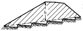
Most North American main lines were built between 1850 and 1920 on embankments that were end-dumped or wagon-placed with little or no compaction, then raised repeatedly by adding ballast. The result is a layered, variable fill that bears little resemblance to a modern engineered embankment.
New fill for sidings, second main track or grade raises should be placed and compacted to the client specification. Typical practice, to be confirmed against the governing client standard:
Evaluate embankment side-slope stability using Chapter 13 methods, with the design train surcharge applied (Cooper E-80 converted to an equivalent strip load, per client criteria). A minimum static factor of safety of 1.5 is the common target (Chapter 1, Section 1.2); confirm with the client. Evaluate settlement of new fill on the foundation using Chapter 12 methods, and design ground improvement where needed using Chapter 17, including the Section 17.16 technology library.
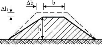
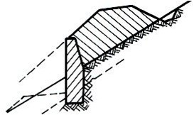
Commonly used embankment side slopes (horizontal : vertical) quoted from Bowles: 1.5–2 : 1 for usual soils and 2 : 1 for gravel and sand and for erosion-prone soils. Slopes must follow from the geotechnical study, and the foundation beneath the embankment must be evaluated as well as the fill.
Figures · click to zoom
After Profillidis (2014), §9.12.2, Figs. 9.14–9.16; slope values after Bowles (2001). Full reference under Supplemental Sources.
Most mainline track is over 100 years old. It was often built without sub ballast, for lighter and slower traffic, by observational methods with a low factor of safety and compaction below modern standards. The core of the original fill can still be loose. Because train loads act mainly to about 5–10 ft below the ties, only the upper few feet reflect later work, and the rest is as built. Construction history is therefore worth recovering before planning a subgrade repair.
Figures · click to zoom
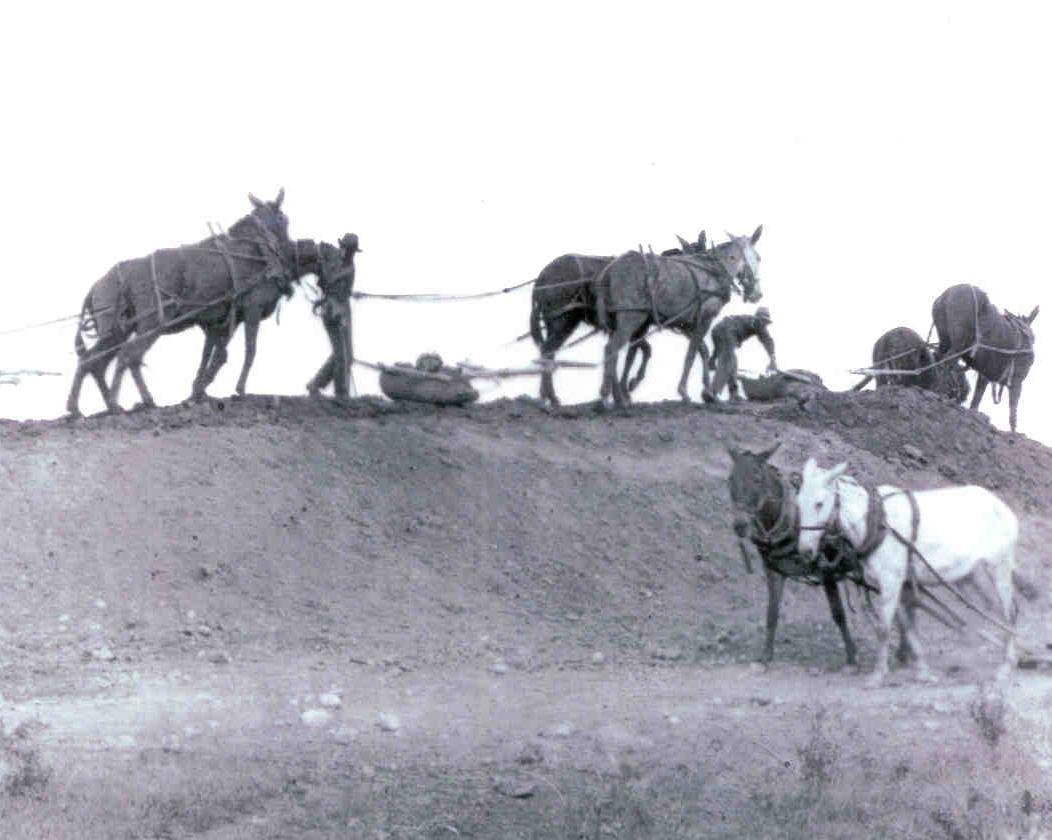
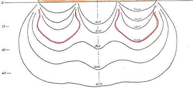
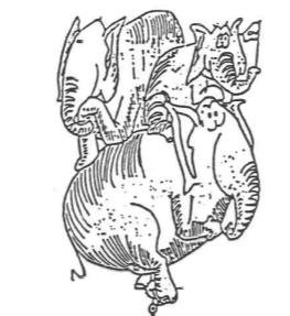
After Geotechnology for Railroaders Program, Module 3; §03. Full reference under Supplemental Sources.
Case study: 3.16.1 Thirty-year-old expansive clay embankments: where the moisture really settles (Look 2023), in §3.16 Case Studies.
Cuts expose natural ground at formation level, where it is subject to groundwater seepage and repeated loading. Common issues:
Investigation in cuts should include borings or test pits at formation level. Also measure groundwater levels over time (Chapter 9), and test swell potential where the soil is plastic (ASTM D4546; ASTM D4829 for expansion index).
Before excavating a cut, study the geological formations along it, particularly the joint pattern (“diaclases”), so as to disturb the existing equilibrium as little as possible. Design should balance safety, cost and fit with the surrounding landscape. Commonly used cut slopes (horizontal : vertical) quoted by the book are:
| Material | Slope |
|---|---|
| Silt | 2.5–3 : 1 |
| Muddy (silty) sand | 2–3 : 1 |
| Gravel | 1.5–2 : 1 |
| Stable clay | 1–1.5 : 1 |
Indicative only. The governing slope comes from the site geotechnical study and the stability analysis in Chapter 13.
Protect cut slopes with shrubs or trees, which also blend the work into the landscape, and provide drainage on the slope to prevent softening.
After Profillidis (2014), §9.12.1; slope values after Bowles (2001). Full reference under Supplemental Sources.
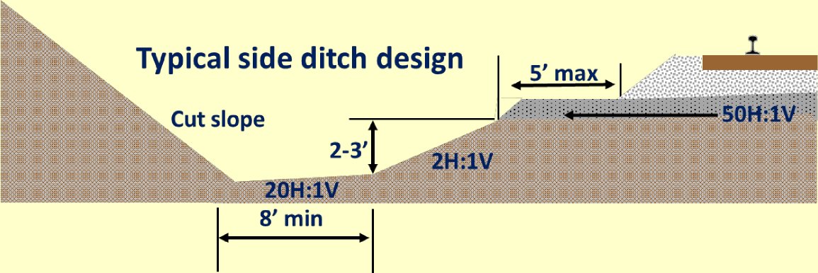
Where the subgrade in a cut sits at or near the water table, seepage softens it and causes uneven settlement. Gravel trench drains, with or without perforated pipe, lower the table; sometimes a permeable sub-ballast layer is enough. In deep soil cuts, cutoff ditches or benches intercept slope runoff and control erosion that would otherwise fill the side ditches. Keep them at a 1–2% longitudinal slope so water moves without accumulating above the cut slope.
Figures · click to zoom
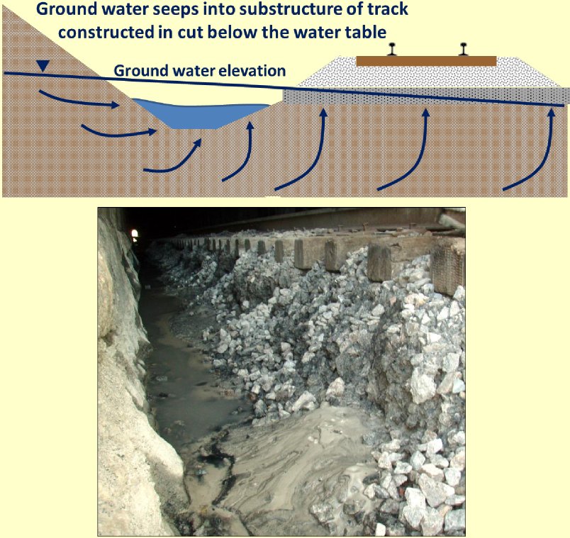
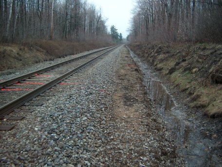
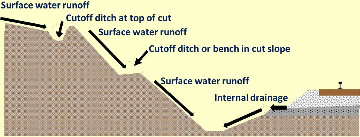
After Geotechnology for Railroaders Program, Module 4; §05, §07. Full reference under Supplemental Sources.
Case study: 3.16.2 Four materials in one 1,300 ft cutting (Look 2023), in §3.16 Case Studies.
Case study: 3.16.3 Earthworks tender assessment for a balanced cut-to-fill job (Look 2023), in §3.16 Case Studies.
The foundation is the natural ground on which the embankment rests. Its behavior controls long-term settlement, deep-seated stability, and the response to new loading such as heavier cars, a second track or a grade raise.
| Foundation Condition | Why It Matters | Key Tests | See |
|---|---|---|---|
| Soft to medium clay | Consolidation settlement; undrained failure under new fill | ASTM D2435 (consolidation), D2166 / D4767 (strength), field vane D2573, CPTu D5778 | Chapters 12, 13 |
| Organic soil, peat, muskeg | Large primary and secondary compression; "muskeg punching" | ASTM D2974 (organic content), D2435 | Chapters 1, 12 |
| Sensitive and quick clays | Brittle failure with little warning; retrogressive slides | Field vane (peak and remolded), D4648 fall cone | Chapters 1, 13 |
| Loose saturated sands and silts | Liquefaction and cyclic softening | SPT D1586, CPT D5778, fines content D1140 | Chapter 14 |
| Collapsible soils (loess, some alluvium) | Sudden settlement on wetting | ASTM D5333 (collapse potential) | Chapter 4 |
| Karst (soluble bedrock) | Sinkholes, raveling voids above bedrock | Geophysics (ASTM D6429 guide), probe borings, rock coring | Chapters 4, 7 |
| Undermined ground | Mine subsidence (sag and pit) | Mine maps, borings to mine level, monitoring | Chapter 4 |
Borings for embankment evaluation should extend through the embankment and at least through the compressible or weak foundation layers into competent material. Use the depth criteria in Chapter 5.
A peat bog forms as vegetation fills a dying lake, and part of it may float on lacustrine soil. Its limited strength comes from intertwined fibers, so ditching or cable plowing that cuts them can turn a quiet section into a problem site. Old track over muskeg often sits on a corduroy mattress of crosswise logs; where it has decayed, peat pumps up through the gaps under traffic. Organic soils can compress by up to about 40%: 12 ft of peat can mean 5 ft of settlement. Excavate thin peat; build over thick peat and let it settle.
On soft clay or peat, an embankment can fail at its base as soft soil squeezes out from under the load. On peat, a stabilizing berm should be about twice as wide as the peat is deep, built in thin lifts over geogrid or woven geotextile, and never placed after removing the peat crust.
Figures · click to zoom
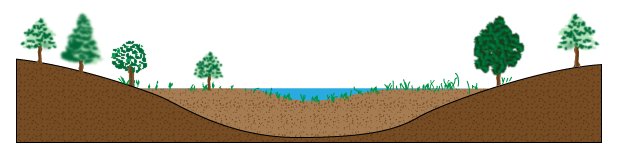
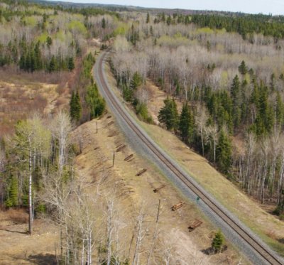
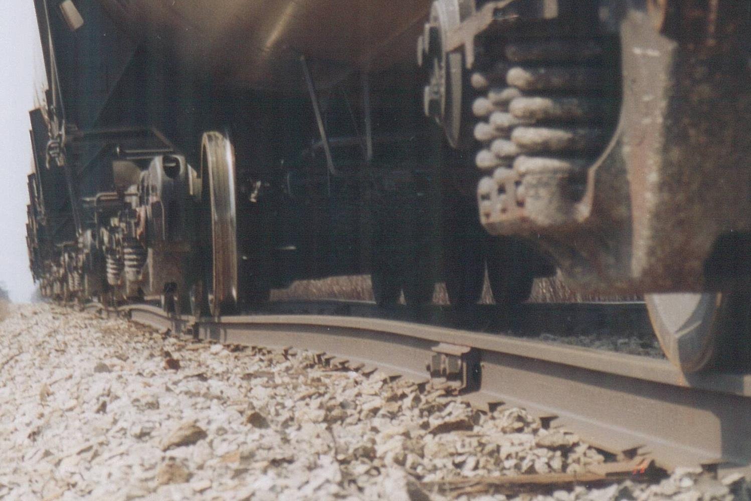
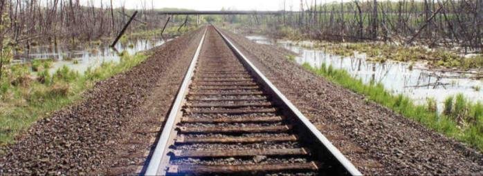
After Geotechnology for Railroaders Program, Module 2, Module 3, Module 5, Module 6.1; Module 2 §07, §08; Module 5 §06; Module 6.1 §03. Full reference under Supplemental Sources.
Water is the common factor in almost every substructure failure. FRA Track Safety Standards require that drainage and other water-carrying facilities under or immediately adjacent to the roadbed be maintained and kept free of obstruction (49 CFR 213.33). The geotechnical consultant evaluates whether the drainage system can do its job and what happens to the substructure if it cannot.
On new construction and rehabilitation, finish ditches, culverts, subdrains and other earthwork near the track before final subgrade preparation begins. Working in that order keeps equipment off the finished subgrade and soil out of the ballast. It also gives the contractor a site that drains while the track goes in.
Construction-phase checks for these items are listed in Chapter 15, Table 15-S1.
After UFC 4-860-01FA (2004), ch. 9, §4b and §4c. Full reference under Supplemental Sources.
Cuts with seepage. Make the side drains deep enough to lower the phreatic surface at least 3–6 ft below the subgrade. The depth depends on permeability, fissuring and pervious seams. Intercept ditches above a cut must not leak into the slope or cut across a critical slip surface.
Ballast pockets that hold water. If severe, reconstruct the substructure. If less severe, reshape the subgrade and replace the subballast and ballast.
After Selig & Waters (1994), ch. 13. Full reference under Supplemental Sources.
Culverts pass water beneath the embankment and are foundation elements in their own right. AREMA MRE Chapter 1 covers culvert types, installation, bedding, backfill and cover. The geotechnical scope typically includes:
Water that can reach the subgrade must leave quickly. Give the top of subgrade a 3–5% crossfall toward transverse and longitudinal drainage devices. The book distinguishes two flows to design for: runoff from the track itself (in cut or on fill) and runoff from the contributing catchment. By the rational method:
| Surface | c |
|---|---|
| Track formation | 0.85 |
| Embankment slope | 0.3–0.4 |
| Impermeable surfaces | 0.9–1.1 |
| Cultivated soils | 0.4–0.8 |
| Sandy soils | 0.3 |
| Forest | 0.2 |
The runoff coefficient is the least certain input and needs judgment. Semi-empirical formulas must be checked against observed flows. For the TGV Méditerranée high-speed line, rainfall-based formulas gave 1–5 m³/s/km² for the 100-year flow, but observed extremes were about 10 m³/s/km². The methods were recalibrated to the observations and the minimum diameter of cross-drainage under the track was set at 39 in.. Because rainfall intensity is increasing, the book suggests return periods well beyond the traditional 50–100 years, up to 1,000 years, with the probable maximum flood as the reference flow.
Figures · click to zoom
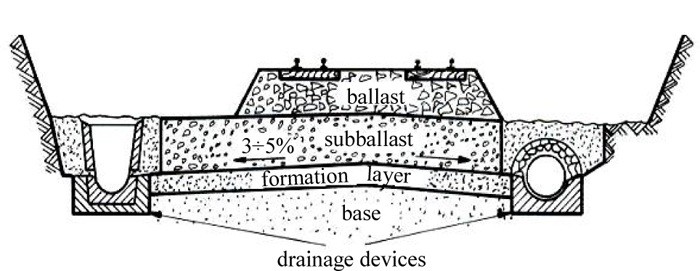
After Profillidis (2014), §9.14.2–9.14.3, Eq. 9.12, Fig. 9.4. Full reference under Supplemental Sources.
Water enters the substructure in three ways: precipitation, surface water (slope runoff and blocked or flooded ditches and culverts), and subsurface seepage. Poor drainage can increase surfacing frequency up to tenfold, increase track buckling 10–30% through loss of shoulder strength, and multiply slow orders. It is deferred because its effects are gradual and are easy to blame on rail, tamping or “soft track.”
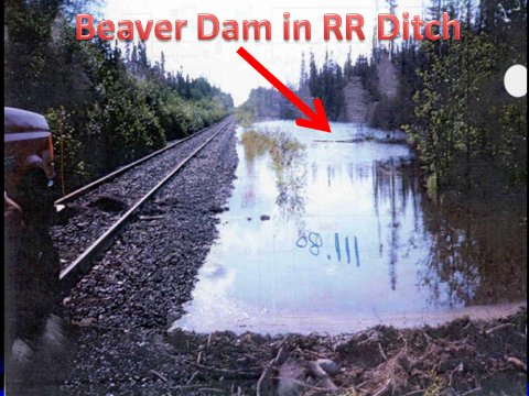
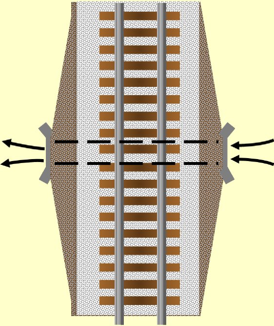
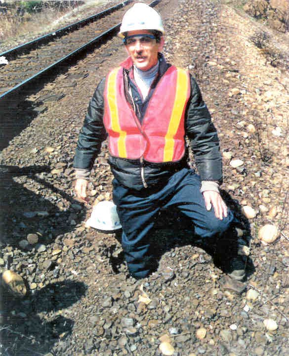
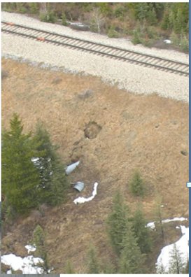
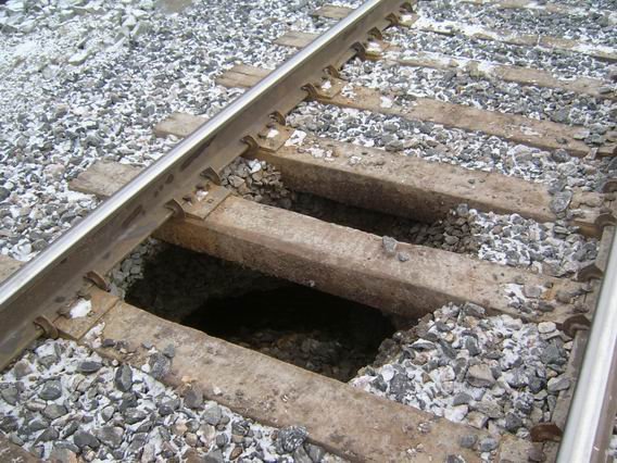
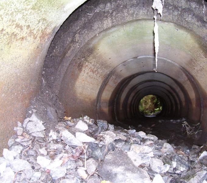
Culverts are the most failure-prone drainage element. Check the inlet for scour, small slope failures, sand fill and open joints; the outlet for erosion, ice plugs and seepage; and the barrel for obstructions (beavers, sand, snow, trees) and sink holes over open joints. Open joints in concrete pipe let soil migrate out, leaving a void that collapses as a sink hole (“turtle hole”). Stone-box and blind-stone drains fail the same way through uncemented joints. Crawling the barrel is the only reliable condition check. Older 100-year sizing is being superseded; the course recommends sizing closer to a 500-year storm at many locations and never using pipe smaller than 36 in.
Figures · click to zoom
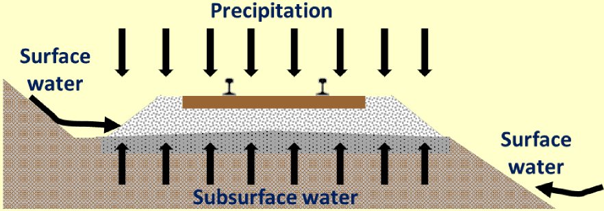
After Geotechnology for Railroaders Program, Module 4, Module 2; Module 4 §02–04, §07, §09; Module 2 §06. Full reference under Supplemental Sources.
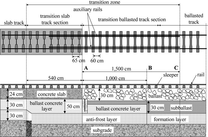
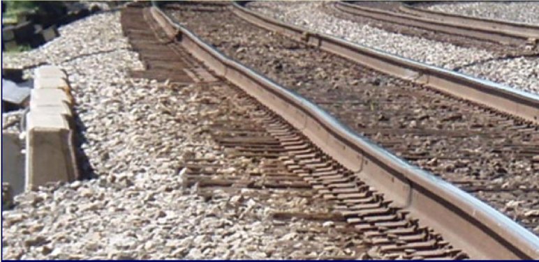
Where ballasted track meets a bridge, a culvert with little cover, a grade crossing, or a direct-fixation or slab track section, support stiffness changes abruptly. Wheel-rail dynamic forces increase at the change and settlement accumulates on the softer side. The result is the familiar "bump at the end of the bridge," which demands frequent surfacing.
Slab track is stiffer and less flexible than ballasted track, and ride quality cannot change abruptly at a single point. The book’s example is the transition for the Rheda slab system (Figure 3-6):
The same principle (graded stiffness over a length, not a step) applies at bridge approaches and at tunnel portals, where the book notes that rubber pads of suitable thickness are placed at the entrance and exit to soften the change felt by passengers.
Figures · click to zoom
After Profillidis (2014), §7.3, §17.7, Fig. 17.11. Full reference under Supplemental Sources.
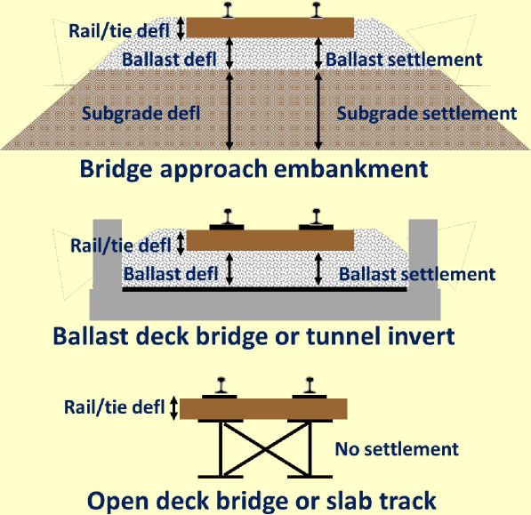
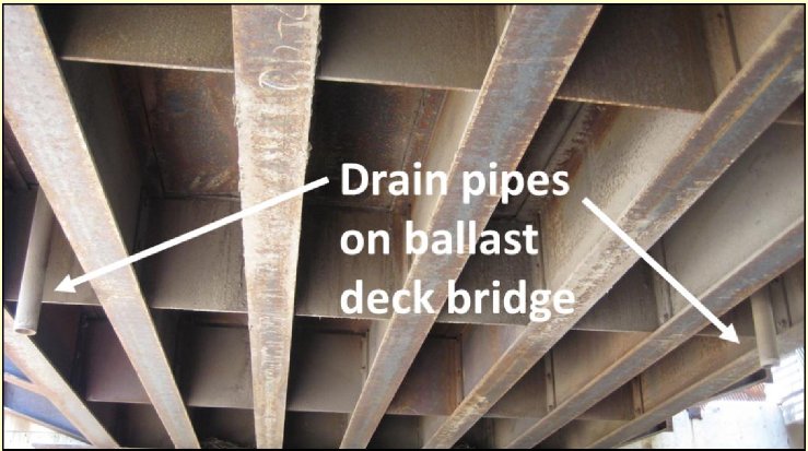
A bridge is stiffer than the track bed leading to it, so approach track deflects and settles more. The low spot that forms at the transition generates extra dynamic load, which deepens the low spot: a self-reinforcing cycle like the mud-spot snowball. Manage it from both sides. Stiffen the approach (for example with geogrid reinforcement) and soften the bridge (a more flexible deck, a ballast mat on a ballast deck, or under-tie pads on an open deck). Aim to minimize the difference in deflection rather than to eliminate settlement. Water management at the approach matters as much as the structural transition; mud pumping between the ties there points to a drainage problem below.
Figures · click to zoom
After Geotechnology for Railroaders Program, Module 3, Module 4; Module 3 §10; Module 4 §05, §09. Full reference under Supplemental Sources.
Bridges, retaining walls, ballast retainers, signal and communication structures and overhead catenary supports all have foundations within the zone influenced by train loading. AREMA MRE Chapter 8 covers the design of concrete structures and foundations for railway loading, and client standards add their own requirements.
| Foundation Type | Typical Railroad Use | Key Geotechnical Inputs | See |
|---|---|---|---|
| Spread footings | Abutments and piers on competent soil or rock; walls; signal bases | Bearing capacity, settlement, frost depth, scour depth | Chapters 11, 12 |
| Driven piles (steel H, pipe, precast concrete, timber) | Bridge abutments and piers; trestle replacement | Axial and lateral capacity, drivability, downdrag | Chapter 11 |
| Drilled shafts | Piers, catenary and signal foundations, walls | Side and tip resistance, lateral response, groundwater and caving | Chapter 11 |
| Micropiles and helical piles | Limited access and under-track work; retrofit of existing structures | Grout-to-ground bond, buckling in soft soils | Chapter 17 (17.16) |
| Sheet piles and soldier piles with lagging | Ballast retainers, temporary and permanent shoring | Earth pressure with train surcharge, embedment, drainage | Chapter 16 |
Any excavation or structure close to an operating track must be designed for train surcharge. Class I railroads publish shoring guidelines that define a live-load influence zone projected from the track. Excavations and temporary works within it require railroad-reviewed design and monitoring (e.g., the BNSF–UPRR Guidelines for Temporary Shoring). Treat the client's current guideline as governing. Lateral earth pressure from the surcharge is evaluated using the methods in Chapter 16.
Scour at piers and abutments is one of the leading causes of bridge failure. Foundations in waterways must be evaluated for total scour (long-term degradation, contraction and local scour) following FHWA HEC-18 and the bridge owner's scour program. The geotechnical deliverable should state the soil or rock erodibility, the scour depth used, and whether the foundation remains stable at that depth.
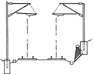
Catenary poles (cast or galvanized steel, prestressed or reinforced concrete) are spaced 164–246 ft, depending on pantograph oscillation, locomotive sway and climate. Excavation and backfill must be done carefully to keep ground settlement to a minimum (Figure 3-7).
On good subgrade the pole is set in an embedded block whose overturning moment is resisted by lateral soil pressure, M = c · B · L3, where B is the block width, L the embedment depth and c a coefficient that depends on the soil (Figure 3-8). On poor subgrade the poles are founded on a concrete slab, typically 6.6 ft × 11 ft at a depth of 3.6–4 ft.
Pole foundations sit in the shoulder, often on embankment edges. They should be included in slope-stability and settlement checks when a shoulder is steepened or a fill is widened.
Figures · click to zoom
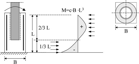
After Profillidis (2014), §20.9, Figs. 20.15–20.16. Full reference under Supplemental Sources.
These locations concentrate dynamic load and trap water, so they fail sooner than open track on the same subgrade.
A turnout lets a vehicle pass from the main track to a diverging track without interrupting its movement. Its parts are the stock rails (fixed), the switch or tongue rails (moving), the frog at the intersection point, set at a frog angle stated as a tangent such as 1:9 and usually made of manganese steel, and the check rails opposite the frog. Turnouts must carry the line’s axle load, impose the fewest possible speed restrictions, resist wear and require little maintenance.
Figures · click to zoom
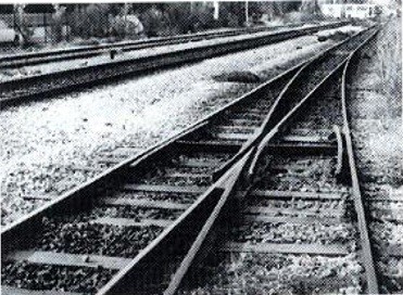
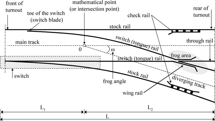
After Profillidis (2014), §13.6, §14.11.2, §15.1–15.2, §16.8, Figs. 15.1, 15.3. Full reference under Supplemental Sources.
Its main North American use is on short problem sections: diamonds, turnouts, bridge approaches, tunnel floors and highway crossings. There are two forms:
Typical underlayment.
Full-depth limitations. Full depth reduces lateral and longitudinal resistance and resilience. It cannot be tamped, which is a serious limitation if the subgrade moves. It is also hard to rebuild. Use it only where those losses are acceptable and geometry adjustment is essentially not needed.
Drainage. Asphalt blocks upward drainage from the subgrade. Where seepage is expected, provide a granular drainage layer beneath the mat. That layer also serves as a construction platform.
After Selig & Waters (1994), ch. 11. Full reference under Supplemental Sources.
Pipelines and utilities crossing beneath the track are third-party foundation elements. AREMA MRE Chapter 1 and client utility-crossing standards govern casing, depth of cover, installation method and inspection. From a ground hazard standpoint:
A fiber-optic cable installation along a shoulder destabilized the slope by breaking nearly every rule at once. Crews excavated at the toe, overloaded the shoulder with spoil, and then left the ditch unmaintained because the cable running through it discouraged cleaning. Support later placed only at the shoulder, with none at the toe, made it worse. For any utility work in the right-of-way: do not excavate at the toe, do not overload the shoulder, keep ditches drained whatever runs through them, and do not let water seep into the shoulder or fill.
Figures · click to zoom
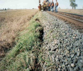
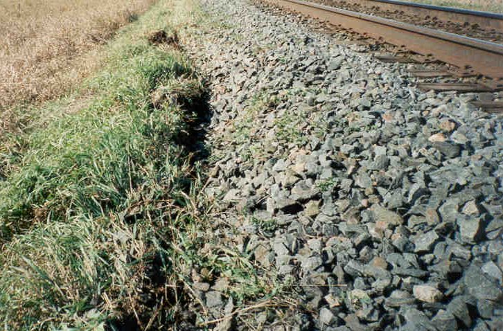
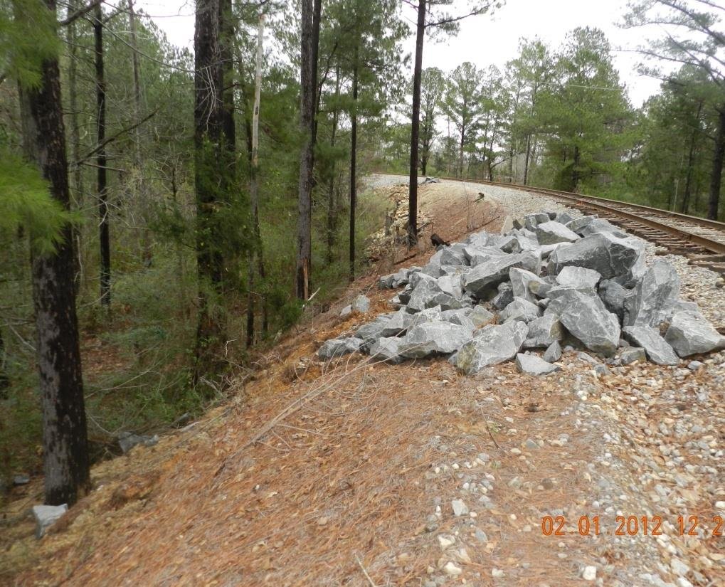
After Geotechnology for Railroaders Program, Module 5, Module 6.1; Module 5 §10; Module 6.1 §03. Full reference under Supplemental Sources.
Case study: 3.16.4 As-constructed drawings that were wrong (Look 2023), in §3.16 Case Studies.
Use this matrix together with the investigation planning criteria in Chapter 5 and the laboratory program in Chapter 10.
| Element | Field Exploration | Laboratory Tests (ASTM) | Deliverable Focus |
|---|---|---|---|
| Embankment body | Borings through crest and shoulders (SPT D1586), CPT D5778, test pits; GPR for bed layering (ASTM D6432 guide) | D2487 / D2488 classification, D4318 limits, D6913 gradation, D2216 moisture | Fill composition, ballast pockets, water in fill, stability |
| Cut floor and slopes | Borings or test pits at formation, groundwater observation wells | D4318, D4546 swell, D4829 expansion index, D3080 direct shear | Softening potential, seepage, slope stability |
| Foundation soils | Borings to competent layer; undisturbed sampling (D1587); field vane D2573; CPTu | D2435 consolidation, D2166 / D4767 strength, D2974 organic content, D5333 collapse | Settlement, deep stability, improvement need |
| Culverts | Borings at inlet, outlet and centerline; camera inspection of barrel; void detection (GPR or probing) | Classification; pH, resistivity, chloride and sulfate (G51, G187, D4327) | Bearing, backfill condition, corrosion, piping |
| Bridge approaches and structures | Borings at each substructure unit; rock coring (D7012 for strength); scour-related sampling | Strength, consolidation, rock strength and RQD | Foundation type and capacity, approach settlement, scour |
| Utility crossings | Locate and verify depth; borings along the alignment; monitoring points | Classification, moisture, groundwater | Settlement and heave limits, monitoring plan |
Foundation elements are ultimately judged by their effect on track geometry. FRA 49 CFR 213.63 sets surface (profile, cross-level and warp) limits by track class. A foundation that causes geometry to exceed those limits between normal maintenance cycles is not performing, whatever its calculated factor of safety.
| Criterion | Common Target (confirm with client) | Where Evaluated |
|---|---|---|
| Static slope stability, embankments and cuts | FS ≥ 1.5 with design train surcharge | Chapter 13 |
| Subgrade and foundation bearing under cyclic load | FS ≥ 3.0 on undrained bearing (Chapter 2 method) | Chapters 2, 11 |
| Post-construction settlement of new fill | Limited so that geometry remains correctable by routine surfacing; client-specific | Chapter 12 |
| Differential settlement at transitions | Minimized; evaluate over the transition length rather than as a single number | Chapters 2, 12 |
| Culvert and structure foundations | Per AREMA MRE Ch. 8 and the client's structure standards | Chapter 11 |
European practice sets three tiers of geometry limits: intervention values that trigger scheduled maintenance, acceptance values allowed to remain after maintenance, and emergency values that require an immediate speed restriction. FRA Track Safety Standards (49 CFR Part 213) and client standards govern in North America; the European figures are given to show how tight track-support performance has to be.
| Longitudinal defect LD (in.) | Horizontal defect HD (in.) | Maximum speed (mph) |
|---|---|---|
| ≥ 0.71 | ≥ 0.59 | 87 |
| ≥ 0.79 | ≥ 0.67 | 75 |
| ≥ 0.91 | ≥ 0.75 | 62 |
| ≥ 1 | ≥ 0.87 | 50 |
| ≥ 1.1 | ≥ 1 | 37 |
| ≥ 1.2 | ≥ 1.1 | 25 |
33-ft measurement base. LD = surface (profile), HD = alignment.
| Speed (mph) | Minimum gauge deviation (in.) | Maximum gauge deviation (in.) |
|---|---|---|
| V ≤ 50 | −0.35 | +1.4 |
| 50 < V ≤ 75 | −0.35 | +1.4 |
| 75 < V ≤ 99 | −0.31 | +1.4 |
| 99 < V ≤ 143 | −0.28 | +1.1 |
| V > 143 | −0.2 | +1.1 |
The European interoperability specifications also limit twist to 0.084 in./ft for speeds up to 124 mph and 0.06 in./ft above, adjusted for measurement base length (Figure 3-12), and limit the difference between nominal and actual cant to ±0.79 in..
Figures · click to zoom
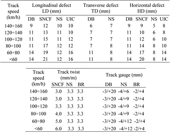
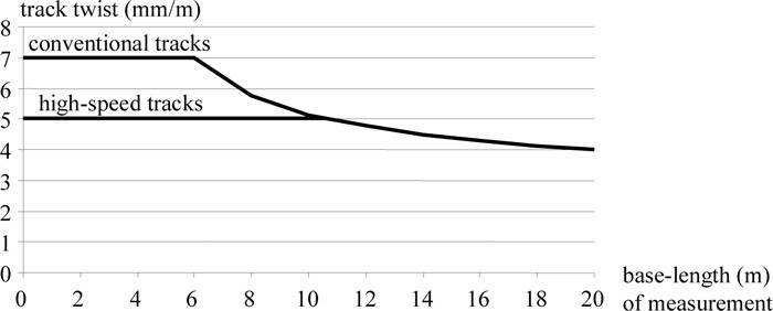
After Profillidis (2014), §16.6, Tables 16.2, 16.4, 16.5, Fig. 16.7. Full reference under Supplemental Sources.
Kelly, Male and Graham hold that options generated in a value study should be compared on whole-life cost. Whole-life cost is the present value of all relevant costs over the investor’s time horizon. Relevant costs include investment (design, construction, fees), operation and maintenance, unplanned repair, planned component replacement, and residual or terminal values at the end of the horizon. Some costs are excluded: trivial amounts, sunk costs already spent, and costs that are the same for every option. Future amounts are discounted with
P = A / (1 + i)n
where A is the future cost, i the discount rate per period and n the number of periods. Inflation is handled with a real rate, i = (1 + bank rate)/(1 + inflation) − 1. In their example, a component costing £6,000 today that will fail in 10 years has a present value of £4,053 at 4 percent with no inflation. With 2 percent inflation the real rate is 1.96 percent and the present value is about £4,941, because the replacement will by then cost about £7,314.
For railroad work: Track foundation remedies often trade first cost against recurring maintenance. Examples are lining a deteriorated culvert versus replacing it, flattening a cut slope versus installing rockfall mesh and patrols, and full subgrade rebuild versus periodic undercutting and surfacing. List each alternative’s recurring items over the railroad’s planning horizon: surfacing cycles, ditch cleaning, drain flushing, mesh inspection and repair, slow-order delay costs where the client supplies them, and expected replacement dates. Discount them using the rate the railroad’s finance group specifies, and present the present-value totals with a sensitivity check on rate and cycle length. Exclude money already spent on earlier repairs at the site. Sunk-cost thinking is a common reason a chronic location keeps receiving the same short-lived fix.
Source: Kelly, J., Male, S. and Graham, D. (2004). Value Management of Construction Projects. Oxford: Blackwell Science, pp. 311–314. Summarized and paraphrased. Full reference under Supplemental Sources.
Checklist · Part III · Track Substructure
| Topic | See Also |
|---|---|
| Ground hazard classification and risk rating | Chapter 1 |
| Ballast, subballast and subgrade design; stress at top of subgrade | Chapter 2 |
| Failure mechanisms and triggers | Chapter 4 |
| Investigation planning and boring depths | Chapter 5 |
| Groundwater characterization | Chapter 9 |
| Laboratory testing program | Chapter 10 |
| Bearing capacity and deep foundations | Chapter 11 |
| Settlement analysis | Chapter 12 |
| Slope stability analysis | Chapter 13 |
| Construction monitoring and compaction testing | Chapter 15 |
| Retaining structures and train surcharge | Chapter 16 |
| Ground improvement methods and technology library | Chapter 17; Section 17.16 |
Q1. A main line shows a cross-level defect that returns within months after each surfacing at the same location over a 60-year-old fill. List three foundation elements you would investigate, and the first piece of client data you would request.
Answer:
Q2. Why should new fill be benched into an existing embankment when a second track is added?
Answer:
Q3. A corrugated metal culvert under 25 ft of fill shows track settlement directly above it. Name two mechanisms that could cause this, and the tests or inspections that would distinguish them.
Answer:
Q4. What FRA regulation establishes the drainage maintenance requirement relevant to foundation elements, and what does it require?
Answer:
Field case studies by Burt G. Look, from Earthworks: Theory to Practice – Design and Construction (CRC Press/Balkema, 2023), chosen for this chapter’s topics. Each is summarized from the book with its key figures and a closing note on railroad application added by the authors of this manual. Credit for the case material belongs to Look; see item S5 under Supplemental Sources.
Related section: 3.2 Embankments
Earthworks for the 4.4 mi Cooroy Bypass, north of Brisbane, were in highly reactive clays (weighted plasticity index 2200–3200). In 1990, time domain reflectometry (TDR) probes were installed in two trenches about 4.3 mi apart in existing 30-year-old embankments of the same clay, built at MDD and OMC to the specification of their day (Look and Reeves, 1992). Findings:
Recommended design: subgrade CBR 3%; target density 92%–94% of standard MDD with characteristic limits of 90%–96%; target moisture 110%–130% of standard OMC. A three-section trial embankment placed at 1.0, 1.2 and “as wet as possible” times OMC converged to a similar moisture within nine months, again 110%–130% of OMC, confirming the approach. During construction, TDR probes and horizontal profile gauges set the curing period before the pavement went on.
Key lessons: zone the clay, with a 8.2 ft side zone matching the measured movement from the batter; specify an upper density limit so that compaction at or above 100% MDD fails for these clays where rainfall exceeds about 39 in a year; target the equilibrium moisture; and allow curing before final layers.
For railroad work: fat-clay embankments on many North American lines show the same seasonal movement, expressed as recurring surface and cross-level defects. When rebuilding or widening such fills, compacting the clay hard and dry is not conservative.
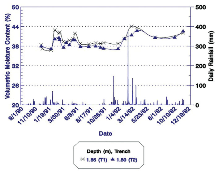
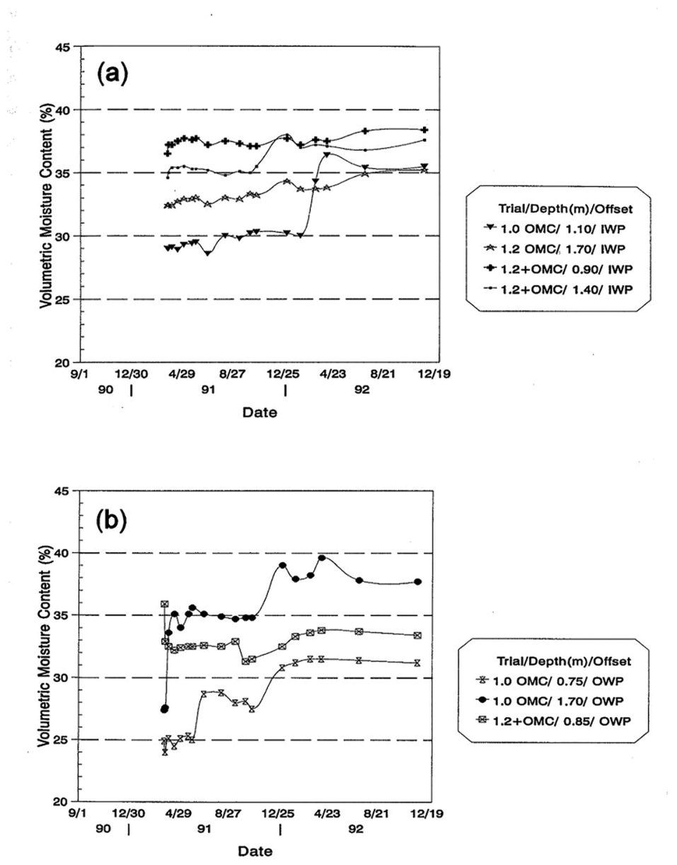
Source: Look, B. G. (2023). Earthworks: Theory to Practice – Design and Construction. CRC Press/Balkema. Case study §10.15, pp. 360–366. Summarized and paraphrased; figures reproduced for internal reference. Full reference under Supplemental Sources.
Related section: 3.3 Cut Sections and Cut Slopes
A cutting of about 392,000 yd³ was to supply embankment fill. Over 1,310 ft its cross sections showed four material types, defined so estimators could plan equipment:
The preliminary borings no longer lined up with the final alignment. Transport bulking ranged from 20% to 70%, and from 0% to 30% after compaction. Types 1–3 behaved as “soil” once compacted, controlled by density testing. Type 4 was suitable as rock fill and could have been crushed on site for drainage or pavement material, but a nearby quarry made that uneconomic.
For railroad work: the same breakdown suits a rail cut balanced into fill. Re-check the borings against the final alignment and have each material type carry its own excavation method, bulking factor and end use. The tender view of this same cut is in the next box.
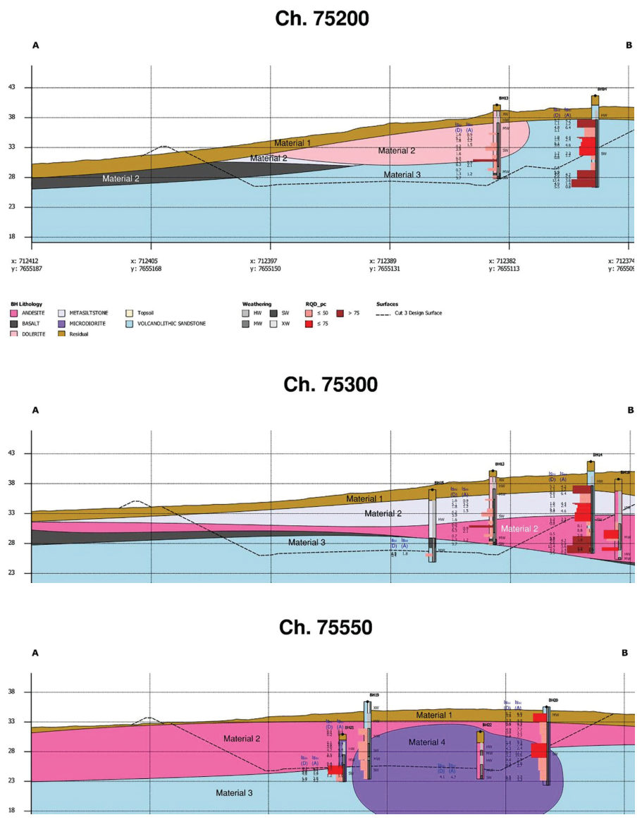
Source: Look, B. G. (2023). Earthworks: Theory to Practice – Design and Construction. CRC Press/Balkema. Case study §8.9, pp. 268–270. Summarized and paraphrased; figures reproduced for internal reference. Full reference under Supplemental Sources.
Related section: 3.3 Cut Sections and Cut Slopes
Look follows the same Cut 3 into the tender stage of a “balanced” job with six cuttings feeding the embankments. The quantities were bank volumes. Each cut had its own rock type, quantity and quality, and had to be assessed on its own merit from source to destination. For each material type the contractor set out depth, class and the best equipment, from scrapers in the top 6.6 ft to a D9 for rock fill between about 16 and 43 ft.
The assessment ran in three steps: excavation; bulking and transport; and placement. Transport bulking and post-compaction bulking have to be treated separately. The balance quantity for each source, its location, matching sources to nearby fills, and zoning of the embankments all formed part of the assessment.
For railroad work: a rail grading contract that is “balanced” on bank volumes can still come up short once bulking, breakdown and material zoning are counted. Ask bidders to show the assessment by source and material type.
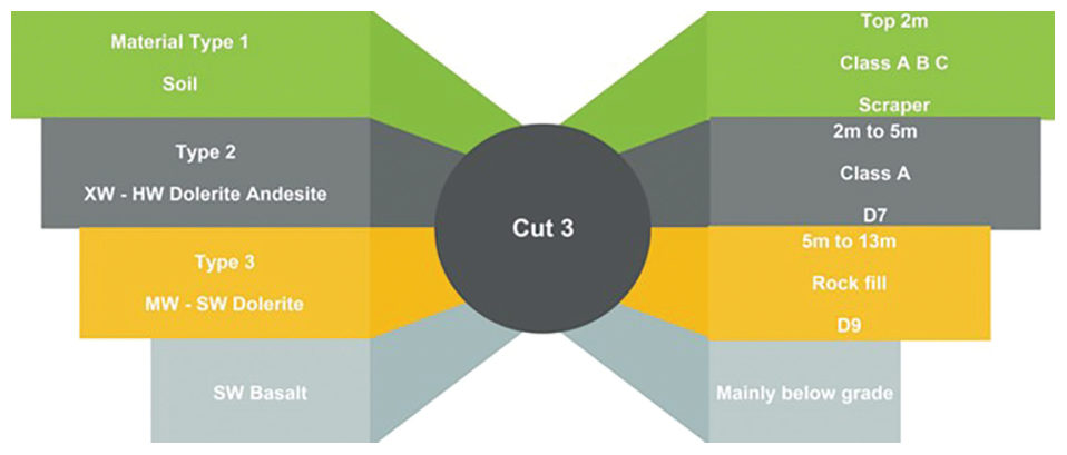
Source: Look, B. G. (2023). Earthworks: Theory to Practice – Design and Construction. CRC Press/Balkema. Case study §14.14, pp. 550–552. Summarized and paraphrased; figures reproduced for internal reference. Full reference under Supplemental Sources.
Related section: 3.9 Utility and Pipeline Crossings
As-constructed drawings are assembled at the end of a project, from second- and third-hand notes, when funds are nearly spent. Look gives three examples from his early site-investigation career:
For railroad work: railroad corridors carry fiber, signal cable and pipelines installed by others over a century or more, often under old permits with poor location data. Treat records as a starting point, pothole or vacuum-excavate before drilling within the right-of-way, and ask track and signal forces what they know about the location.
Source: Look, B. G. (2023). Earthworks: Theory to Practice – Design and Construction. CRC Press/Balkema. Case study §3.7, pp. 90–92. Summarized and paraphrased; figures reproduced for internal reference. Full reference under Supplemental Sources.
Sections on this page marked “After Profillidis (2014)” draw on the document below. Text is summarized or paraphrased; tables are transcribed or reproduced with their original source noted; figures and photos are reproduced from the cited document for internal reference use. Consult the original document before relying on a value for design. Blocks marked “After UFC 4-860-01FA (2004)” draw on item S3 and are rewritten for railroad clients. Blocks marked “After Selig & Waters (1994)” summarize item S4 for railroad clients; tables are condensed from the book and its figures are not reproduced. The Case Studies section summarizes case studies from item S5 by Burt G. Look; its figures are reproduced from the book for internal reference use, and the closing “For railroad work” note in each case study is added by the authors of this manual. Blocks tagged “Project management” summarize methods, examples and figures from the project-management, estimating and construction-management books listed here, applied to railroad work; the closing “For railroad work” note in each block is added by the authors of this manual.
Authors: Daniel P. Colwell and Mario Ruel. This part was written and compiled by Daniel P. Colwell and Mario Ruel for Railway Ground Hazard Risk Management.
Technical content is drawn from the published sources below, and credit for that material belongs to their authors and publishers. Tables, equations and figures taken from a specific source are also cited where they appear.